Arion SAD-1 Analog Stereo Delay Technical Details
There isn't much on the internet about this particular relatively unknown but nice
sounding analog delay, so I have gathered all the information I could find on it from various
forums, data sheets and looking at my own mid-80s SAD-1. This page will not go into any great depth on how the
pedal works, just a detailed overview of what's "under the hood". If it is practical, I may make a DIY
version of this circuit that would fit into a Hammond 1590BB enclosure,
depending on the availability of the IC chips that it uses. Small Bear Electronics has some of the
BBD delay chips that this circuit uses, currently priced at $16 each.

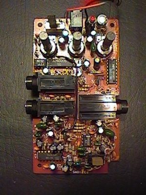
Below is a picture of the PCB, removed from the enclosure. This is how it sits in the plastic enclosure when you are using the pedal. Input jack is on right, outputs on left. DC power jack is at top.

The SAD-1 uses one MN3205 BBD low noise delay chip which is driven by a single MN3102 clock
driver chip. The MN3205 delay chip is capable of delay times ranging from 20.48mS to
204.8mS, although it seems that the SAD-1 somehow accomplishes a little greater delay
time than 204.8mS, but I don't know how to verify that. These two IC chips are located
directly above the output jacks. Directly to the right of the MN3205 and MN3102 are two
trimpots, one for setting bias and the other one for setting clock bleed through.
The echo time is set by a 33K resistor + delay time pot value + 33K resistor + 68pF capacitor.
The power supply required for the MN3205 is 5V, which probably explains why the SAD-1 will
not work with other pedals sharing the same power supply as the SAD-1, because the virtual ground
created in the SAD-1 is not the same as the ground in most guitar pedals using a 9V battery.
Just to the right of these two chips and directly above the input jack is an NEC4027,
which is apparently a CMOS dual flip-flop IC chip. This is used for
switching between bypass and effect on modes. Some other SAD-1 circuits use a
TC4027 chip here instead. A TA75558S dual opamp is connected between the depth control wiper
and the OUT 2 jack, and is
in a single in-line package located in between the two output jacks. Directly below the input
jack is a TA7558P dual opamp in a dual in-line package, which is connected to the output section of the circuit, one opamp
section per output jack. At
the lower left corner of the PCB is an NEC uPC1571 compander chip which is probably included
in the circuit to help keep noise levels reasonable. Feedback, buffers, boosters, etc. are all
transistor based and are rather uncommon C1815 general purpose NPN transistors with a typical
Hfe of around 120. Some PCBs use different chips and transistors than the ones noted above, but they
all appear to use the same NECuPC1571 compander chip. Curiously, the
SAD-1 makes use of zero ohm resistors instead of jumpers, a feature not usually found on less
expensive pedals. The capacitors used appear to be mylar film, ceramic and electrolytic types. As far as
hardware goes, the switches are the most likely thing to fail, followed by the input and output
jacks, although they appear to be fairly well soldered to the PCB. The pots used are really more
like high grade trimpots than the kind of pots DIY stompbox builders are used to using.
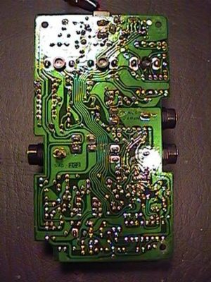
Below is a picure of the bottom of the PCB. It's coated with that usual green stuff you see on
commercially manufactured PCBs, but it looks like it was applied by hand, not the high quality
finish that is prevalent today. This however, does not affect the functionality of the circuit in any way.
There were two versions of this PCB, one is designated as "2C2" and is in a black enclosure, which is the version I have. This version
uses 536 type transistors instead of the C1815 type. The other PCB type is designated as "1A", and is in a grey enclosure. These markings can be found on the bottom of the PCB, at the input jack.

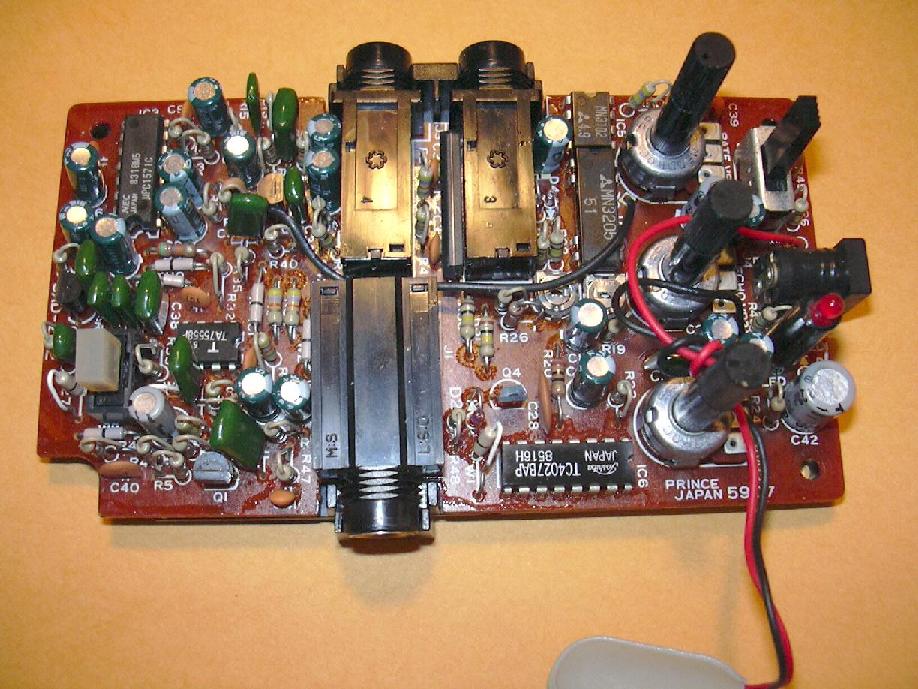
Below is a picture of another individual's SAD-1 PCB showing things a little more clearly than my pictures above.

Arion stereo analog delay pedals are still for sale today, which are now labeled as the SAD-3. I do not know anything about the SAD-3 other than they use a MN3208 BBD chip instead of the MN3205. But, I have heard from some that the maximum delay time is not quite as long as the SAD-1. I have not verified whether or not this is true. These SAD-1 or SAD-3 pedals should last a long time if they are not abused. A lot of people seem to think that because these are in a plastic case that they are easily broken, but the plastic used for the enclosures is pretty tough stuff. The only negative thing about the SAD-1 is that is has a relatively high current draw as a 9V battery will get used up quickly. I use a AC adapter with my SAD-1. All things considered, in my opinion, the SAD-1 is a very good value for the money, if you can find one. But, there is usually one that can be found for sale on ebay if you check for it regularly.