The Technology of the Ebow - Circuitboard
Created 05/20/07
Last updated 06/10/07
By Paul J. Marossy
Here's some photos of the Ebow circuitboard. This is from the PlusEbow, the one that is currently on the market. This information comes from another source, I have only recreated some of what was posted at the Project Guitar forum at one time. This individual obtained this circuitboard for analyzing it in his quest to try and develop a DIY guitar sustainer project. My commentary is in parenthesis.
 |
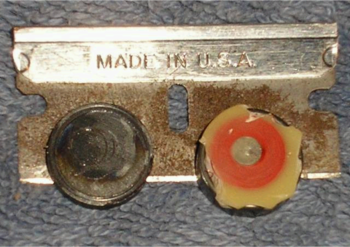
This is one of the coils. It appears to use 42 AWG wire. In the image, you're looking at the back of the coil (ie: the part that faces away from the strings... imagine the razor blade is the strings). The magnet on the right fits on top of the coil. If you look closely, you can see the indentation from that curled up piece of wire. I wasn't able to get a resistance reading on the coil. It was probably damaged in the removal process. That white junk was what the entire inside of the sustainer was potted in. It's pretty hard, but brittle, so I was able to chip a lot of it off. I think it's some kind of two-part urethane. |
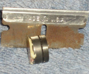 |
This is the assembled coil & magnet structure. Not much to say here, as the picture is fairly self-explanatory. The left side goes towards the strings. |
 |
This is what the coil looks like from the string side. Note that it is wrapped around a core of some sort. I'm not sure if it's steel or magnet, but I'm guessing steel. (I believe this is an Alnico-5 magnet from reading the patent documents). |
 |
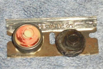
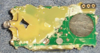
This is the string side of the circuit board with one coil still intact. I've chipped away a substantial amount of potting, but there still isn't much to see. I finally had to give up when I pierced an electrolytic cap and the smell drove me away... d'oh. As you can see, both coils are very similar... I think they're identical. Can you spot the diode I sliced in half? (lower left corner, looks like a 1N914/1N4148) |
 |
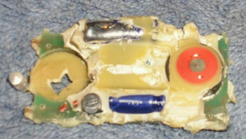
This is the bottom of the circuit board. Not much to see, but you should have a pretty good feel of how the driver/sensing coils are placed. It's hard to be sure, but I think I can make out the footprint of an 8-pin DIP. It would probably be fair to assume there is only one IC on the board, so I'm still wondering how exactly that harmonic switch works. You can see the 3-pin header that I tried to draw above. With all the potting in place, this was the only connection from the circuit to the outside world. Center is ground, other two were +9V depending on whether the switch was in 'normal' or 'harmonic' mode. (I don't think that is correct. I think they are reversing the current in the output coil - otherwise the battery would be shorted) |