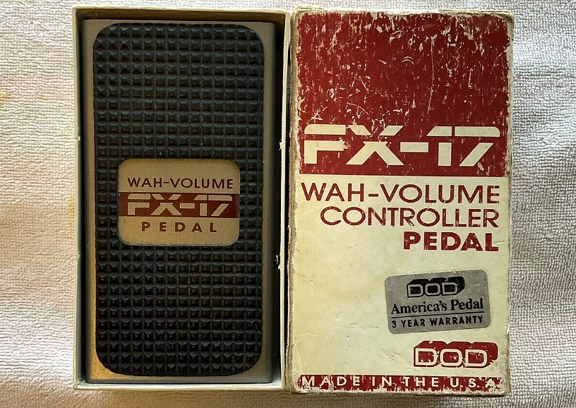
DOD FX-17 Technical Info
Created 9/25/05
Last updated 11/27/09
By Paul Marossy
I bought one of these DOD FX-17 wah/volume pedals from an individual selling one on ebay. One
of the main reasons I wanted one of these was because it was compact, but more importantly,
because it does not have a pot that can wear out and get scratchy. The circuit employed is
rather unique and I think different enough to warrant this technical write up on it.
First of all, these pedals are no longer offered by DOD, but they do offer support in the way of an online instruction manual available at their website. As a volume pedal, it works very well. I like the sweep and it is very quiet - no hissing noise
to be heard. It does send a strong signal to your amp, stronger than a passive volume pedal. As
a wah pedal, it has a rather unique sound to it. It does not use an inductor like the CryBaby,
but is more like a circuit that you would see in a Morley wah pedal. The way a wah sounds to
a guitarist is highly subjective, so I will leave it at that. As a wah pedal, I think it sounds
fine. Not quite as nice as my Maestro Boomerang clone, but more like my Colorsound inductorless wah clone. In addition to being a wah/volume pedal, it also can be a 0 to +5V controller for use
with a synthesizer or other devices. I don't fully understand how this circuit works, but the
schematic linked below should satisfy the curious. I have also included a link below that gives a rough description of how the circuit works.
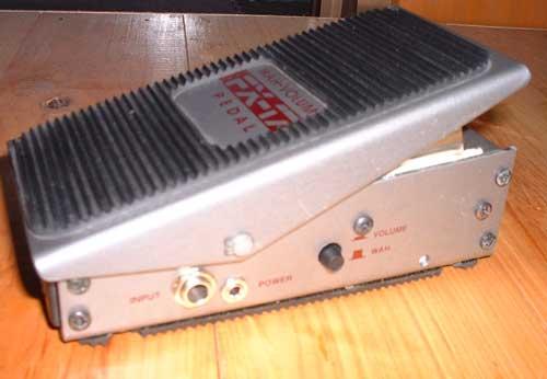 |
This is a very heavy duty pedal, and it is fairly heavy for a small pedal - it weighs in at about 1.5 lbs. The material of the casing appears to be brass, but I am not real sure about that. Overall size is 5"x3"x2" high. |
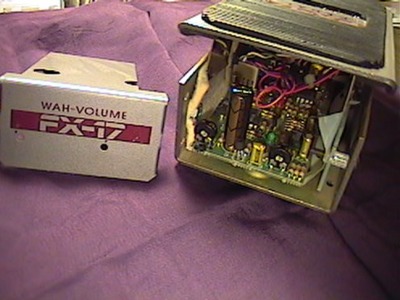 |
Here is a peek under the hood. This cover is held on by four screws, two on each side. Notice the two holes for adjusting internal trimpots. More on that later... |
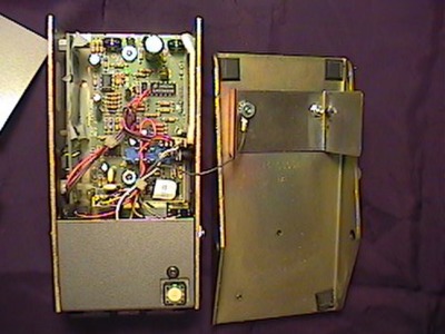 |
Here is the foot paddle removed. It is fastened to the bottom half by a rod with retaining clips at each end. Notice the switch for the wah pedal at lower right of the bottom half. In wah mode, the footswitch is at the heel down position - the opposite of most wah pedals. The battery compartment is in the area below this footswitch. |
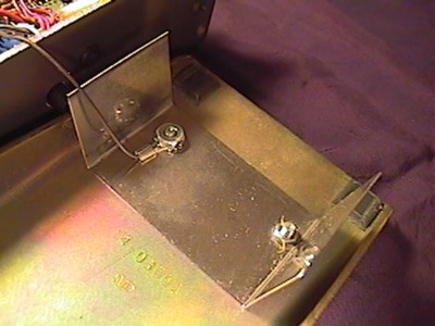 |
This wire grounds the foot paddle and that U-shaped piece of steel which is one of the keys to how this pedal works. |
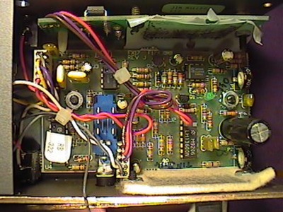 |
This is the PCB. For IC chips, there is a pair of 4007s, a 13600, a LM358 dual opamp and a LM3080 OTA (Operational Transconductance Amplifier). The blue assembly at the bottom of the picture is the wah/volume switch. The side mounted PCB contains the other key part of what makes this pedal work. The felt pad opposite of this PCB provides some resistance to enable the foot paddle to stay where you put it. At far right there are two trimpots which are some user adjustable controls. More on that below. |
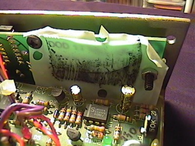 |
This is a close up of the plastic that is sandwiched between the U-shaped piece on the foot paddle and the side mounted PCB. The dark area gives you an idea of the shape of the unetched area of the PCB that lies underneath. The material appears to be Mylar and it looks to be about 2 mils thick. |
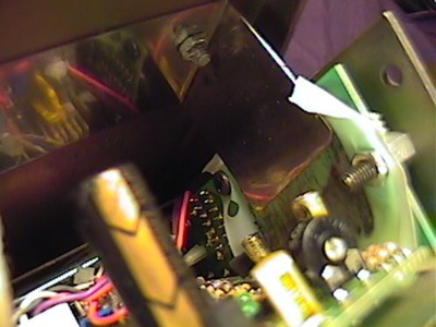 |
And here it is, the key to how this pedal works. When the pedal is assembled, that U-shaped piece attached to the foot paddle, the side mounted PCB and that piece of Mylar form a variable capacitor, the Mylar being the dielectric. The position of the foot paddle determines how big that capacitor looks to the rest of the circuit in wah mode. |
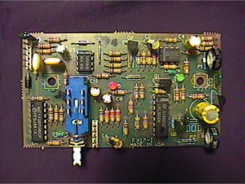 |
This is the main PCB removed from the enclosure. It's a single sided board. |
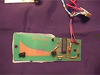 |
This is the secondary PCB which makes up part of the variable capacitor. It's connected to the main PCB with three wires and a connector. |
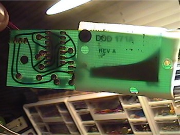 |
With some illumination from the back, you can better see the shape of the unetched part of the PCB that comprises part of the variable capacitor assembly. |
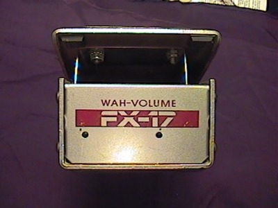 |
There are two holes in the cover to enable adjustment of the internal trimpots. The one on the right controls the minimum/maximum volume level and the one the left adjusts the wah sweep. |
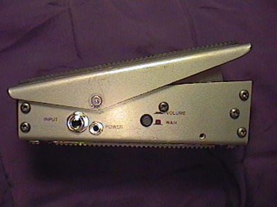 |
This is the right side. The input jack and DC power jack are on this side, as well as the wah/volume switch. |
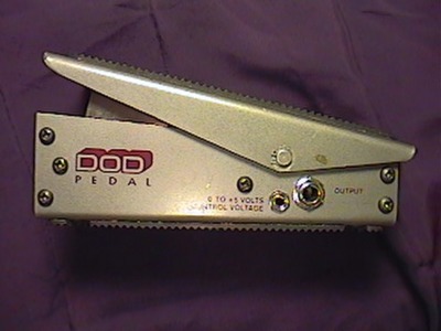 |
And this is the left side. The output jack and the jack for the 0 to +5 volt jack can be found here. |
If you're looking for a good active volume pedal, I would recommend that you give this one a try. As a wah pedal, it has a distinctive sound, which may or may not be what you're looking for. I personally don't see myself ever getting rid of this pedal unless it dies in service or something.
