Building a "Radio-Head" Tube Preamp
Last
updated 3/18/06
By Paul Marossy
This project came into being simply because I had some old radio tubes that were given to me - a 12BA6 (remote cutoff RF pentode) and a 12AT6 (duo-diode hi-mu triode). The Radio-Head was created by an individual in Argentina who goes by the name "Gringo" at the diystompboxes.com forum. He built this preamp around these tubes because they were easily obtainable where he lives. I decided to build this circuit as well, just so I could do something with these old tubes that I have. I made a few modifications to the circuit to suit my own tastes, which entails mainly the coupling cap sizes and the cathode bypass cap sizes. This preamp has quite a bit of gain as I have built it. Below are some details of this project.
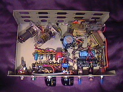 |
Here I have used another recycled data switch box of some sort that I had picked up at a thrift store for a project such as this. This project follows roughly the same layout as my Real McTube project with a few exceptions due to the case geometry. |
 |
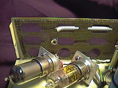
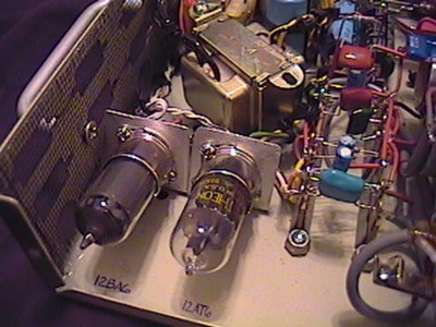
Here is a little closer view of the preamp tubes. The tube sockets are held in place by a couple of brackets fashioned out of some sheet aluminum. |
 |
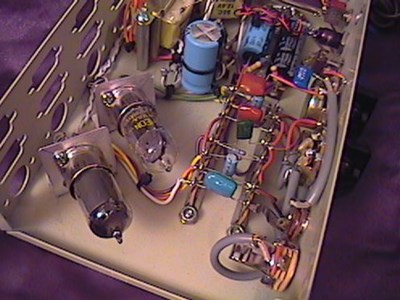
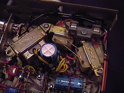
Here is a closer view of the internally mounted transformers and filter caps. The vertical cap at the center of the picture is a 3300uF filter cap for the DC heater supply. I tried an AC heater supply at first, but had some serious hum, so the DC heater section is kind of an add-on to the original layout. There is still a small amount of hum from the heater filaments, but I don't feel it is too objectionable. Perhaps a pair of 2200uF caps as in the Real McTube would work a little more effectively. |
 |
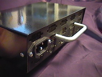
Here is a view from the back. I will install an IEC power socket, the brown cord is just a temporary cord soldered in for my initial testing and tweaking. |
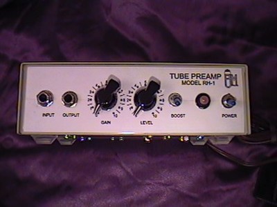 |
Here is a view of the front showing the controls. The graphics are kind of low-tech - a CAD drawing printed out on white paper, glued to the face of the enclosure and covered with clear label protecting tape. The switch second from the right is a boost switch which switches the two cathode bypass caps two ground for more boost. |
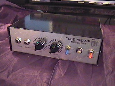 |
About two years after I built this project, I decided that I wanted it to look a little classier, so I decided to paint it and do the graphics over. I like it better this way. |
 |
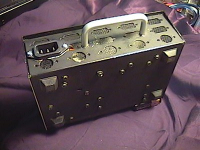
Since I have small children and am planning on making this part of my home studio, the large openings in back of the enclosure bothered me - little fingers could get in there and get a shock. To make it safer, I used some metal window screen, glued to the enclosure with SuperGlue. |
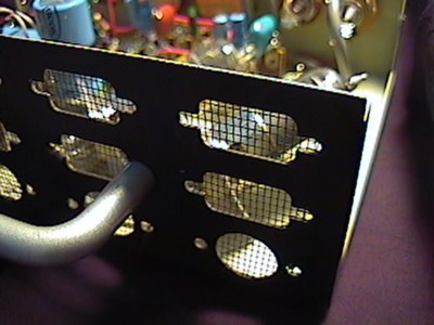 |
Here's how the screen looks from the exterior. It was a pain in the neck glueing it to the enclosure, but the use of a needle and thread to hold the screen down while glueing it was a big help. All in all, this part turned out pretty well. |
 |
I also thought it would be nifty if it had a little carrying handle, so I added one. I used a drawer handle that I've had sitting around for ten years or so. It finally found a home again. |
 |
The bottom half of the enclosure got a coat of flat black paint. |
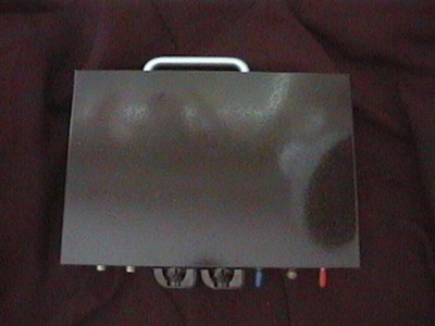 |
And finally, this is a view of the top. I used gloss black spray paint for the top half. It turned out really well. |
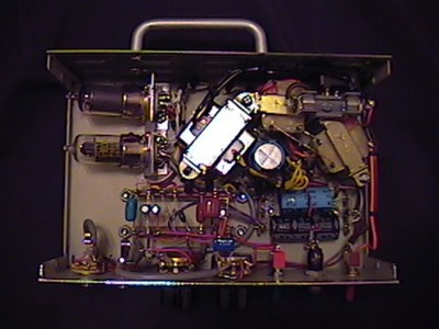 |
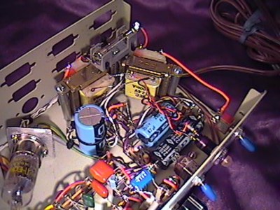
Still not completely satisfied with the sound, I decided to redo a few things. The back to back power transformers had too much loss to give a good B+ voltage, so I decided to add an additional transformer just for the tube filaments. The back to back transformers are now functioning as a 1:1 isolation transformer, albeit, and inefficent one. But this worked out perfect for my purposes as it raised the B+ voltage by about 60 volts. Obviously, I had to rearrange things a little bit to fit the new transformer in there. |
 |
The transformers used are as follows: the back to back transformers are RadioShack #273-1385B, 120VAC/12.6VAC 300mA and the filament transformer is RadioShack #273-1365A 120VAC/12.6VAC 450mA. This arrangement gives me a B+ voltage that is much closer to design - 150VDC with a 122VAC input. This works out perfect and it sounds a whole lot better now. The filament voltage is higher now, too, so that is also a plus. In spite of the filament transformer being close to the circuitry, this preamp is amazingly quiet. |
 |
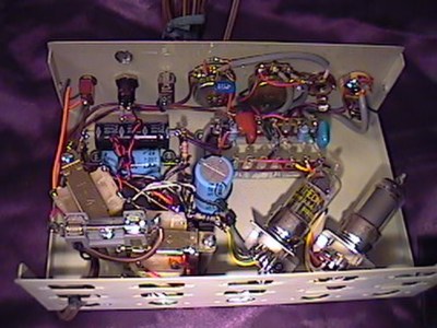
Here is a view of the relocated tubes and sockets. Now I am finally happy with this thing. It sat on the shelf for a long time, so you know how it is, "outta site, outta mind". Definitely was worth the trouble of tweaking it a little bit more, though. |
The sound of this circuit is comparable to the Real McTube, but it has a little different flavor to the input pentode / second stage triode combination. With the boost switch on, there is some serious gain! It should be noted that my schematic shows only 3.3uF caps on the cathodes of the 12BA6 and 12AT6. The way I actually have it wired is with the originally specified 0.68uF caps on the cathodes at all times. The 3.3uF caps are wired in parallel and the boost switch makes or breaks the connection to ground on those caps.