The Shaka Tube In A Hammond 1590BB Enclosure
The Shaka Tube Saga Continues
Last
updated 7/14/05
By Paul Marossy
This is the third time I have built the Shaka Tube circuit. My original "Bulldog" didn't work exactly as planned. Then I rebuilt it, and it worked great, but I have felt for a while that the circuit could be built into a smaller enclosure, specifically, in a Hammond 1590BB. It was a challenge to find a way to fit all the parts into the enclosure following my usual placement of jacks, pots and switches, but thanks to the use of AutoCAD, I was able to overcome those challenges. This new layout basically follow the layout of my Bulldog, except for the location of the tube. Below is a few pictures with commentary.
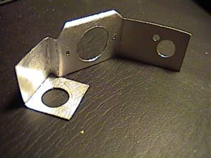 |
The main obstacle was placement of the preamp tube. My layout required me to place the tube at an angle inside the enclosure. This in turn required some sort of bracket for holding the tube socket. I fashioned one out of a piece of aluminum sheet. I used a piece of paper bent up in various ways to find the best way of making the bracket. When I found what worked the best, I used it for a template for the real one. I drilled all of the holes after I did all the bending. It was a pain in the neck doing it like that, but I did it successfully. |
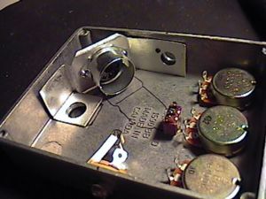 |
Here is a view showing how the bracket will be held in place in the enclosure. The bypass switch and input jack will hold it in place. |
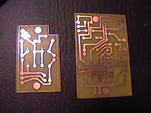 |
Here, I have just etched the PCBs. One of them had a small mistake which I have corrected. |
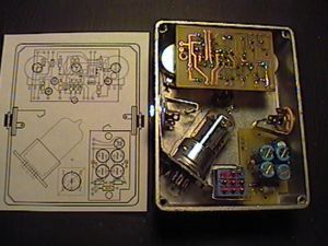 |
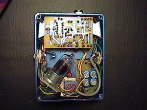
Here is a view showing how all the parts will fit in the enclosure. It's a bit of a squeeze, but it all fits. |
 |
Here is a view of the finished interior. At this point, all of the wiring is complete. I never paint the inside of the enclosure, but on this project, I decided to try something new. |
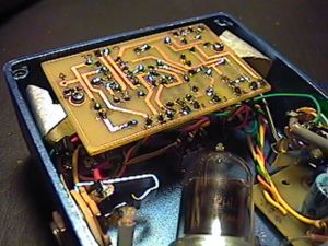 |
I fashioned a couple of brackets out of sheet aluminum to secure the main PCB in place. The pots hold the brackets in place. I cut the brackets with a Dremel Tool as required so that they fit in between the components on the PCB without possibly shorting anything. |
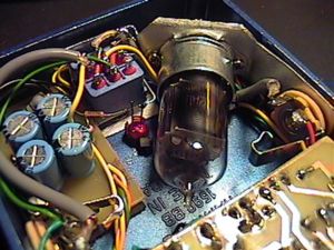 |
Here is a close up of the tube socket bracket. I had to drill one more small hole in the bracket for the wires from the tube socket to pass through to the main PCB. The power supply PCB is held in place by the bypass switch and output jack. Bias adjustment is also on this board, adjacent to the output jack. Underneath the PCB is some 1/16" self-adhevise neoprene foam rubber to keep the PCB from shorting out on the enclosure. |
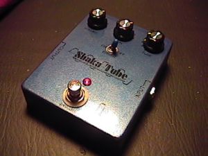 |
This is how it looks on the outside. This picture doesn't capture its true color, a metallic cobalt blue. This enclosure doesn't have ventilation holes like my other Shaka Tube build. Since this hasn't been a problem for others who have built this circuit, I guess I'll settle for leaving it as is. | 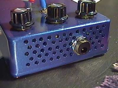 |
About six months after I was finished with this project, I decided to drill some ventilation holes in the enclosure. I don't think it's really absolutely necessary, but it makes me feel better. To drill the holes, I just laid out a 1/4" grid with an extra fine point Sharpie. Then I marked where to drill the holes with a regular Sharpie, alternating the location of the holes in each row. Then I stuck the enclosure in a vise and drilled away with a hand drill fitted with an 1/8" drill bit. This also required me to repaint the enclosure, which I wanted to do anyway since I wasn't completely satisfied with the color of the paint. This picture shows the true color of the paint, but doesn't quite capture the metallic quality that it has. |
I am happy with the result of my efforts. And it
feels good to have overcome all the obstacles in making all of this stuff fit neatly into the enclosure
that I wanted to use. Being a mechanical engineer, it's hard to walk away from a technical challenge like this!
On my original PCB layout below, there was one mistake, which I have corrected. The 0.01uF cap that was connected to Pin 7 actually needed to be connected to Pin 6. My own Shaka Tube was built with this same mistake, which I have since corrected. This was an easy fix - I just cut one trace and soldered in
a little jumper to the correct trace.
Just a few notes on the performance of this pedal as I have it laid out. I initially had a little concern that I might have a some hum due to the relatively close proximity of the tube to the input and output jacks. In my testing/debugging process, I did notice that I had a little bit of hum due to an unshielded wire that ran from the bypass switch, under the preamp tube and to the input of the circuit. And, I had another unshielded wire that ran from the bypass switch the volume pot which ran in parallel with the AC wire to the power supply board. So, I decided to change those to shielded cable, and now I really can't hear any hum at all. So, all that to say, if you use a similar layout to mine, use shielded wire on the input/output jacks, and the wires to the input and output of the circuit.
A note about changes I made on this build that differed from my first Shaka Tube build. On that earlier build, I used a 390pF cap in parallel with the gain control instead of the specified 250pF and a 4.7uF cap after the 220 ohm resistor connected to Pin 2 of the opamp instead of the 2.2uF as specified on the schematic. Also, I used a 50K pot for the tone control instead of the 100K as specified and a TL071 opamp instead of a TL072. On this latest build, I built it exactly per the schematic, and I think this one sounds better than my earlier one does. It seems to sound a little more articulate. I used a grounded circuit input true bypass on this one, too. While this Shaka Tube was built using the PCB layout below, while I was building it, I actually modified it for use with a TL072 instead of the TL071 indicated on the PCB layout.
Which leads me to how it sounds: killer! Seriously, I just love the way this one sounds with a NOS RSD 12AT7 tube that I recently acquired (German manufacture). I think this thing has as much gain as the new manufacture 12AX7 I had in it for testing, but it sounds better. Out of curiousity, I measured voltages, too. Here is what I had: Since my 13VAC 800mA wall wart puts out 15 volts when attached to this circuit, I used a 10ohm resistor in series with one leg of the power supply to get me 12.8VAC. On V+, 11.8V, V-, -14.6V and bias -13.6V. This is where I think it sounds the best to me.
7/14/05: A PCB layout using a TL072 has been added in addition to the one utilizing a TL071.
9/9/06: Mistake in TL072 PCB layout corrected.