DIY External Bypass-A/B Pedal
Last updated 10/4/02
I am always finding ways to recycle old junk and turn it into something cool. I once saw a thread at a guitar effects forum talking about sewing machine "stompboxes". That gave me an idea... I was considering building a bypass switch box because I thought it could come in handy sometimes. With this box, you can have a external true bypass. It can also double as a switchable "Y" connection. In other words, with the same pedal, you can switch between different guitar amps just by stepping on the switch, depending on what jacks you plug the cords into. This can come in real handy when you have two different amps to practice on, but you don't want to have to switch cords around all of the time. It has lots of uses.
So, one day at the local Goodwill thriftstore, while I was rummaging for a good deal on whatever, I stumbled across a sewing machine pedal minus the sewing machine. So I bought it for a couple of dollars. To make the pedal, I simply gutted it. This means removing the power cord, reed switch and rheostat from inside the enclosure. After that is done, you have some room inside to put some jacks and a battery to light up an LED indicator. I simply drilled 2 holes on each side for the 1/4" jacks and two holes under the footpaddle, where I inserted two sub-mini on-on DPDT switches. When you press the footpaddle, it pushes the switches underneath. I wired one switch to operate a reversing LED. I thought that would be a lot simpler than trying to build some kind of circuit to switch the LED. The LED turns green or red, helping you to keep track of what you're doing. The other switch switches between bypass and effect through modes. I used an existing screw to serve as a set screw to limit the travel of the footpaddle to prevent excessive force on the switches. Some pictures are below.
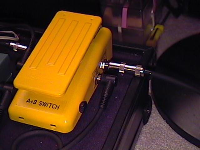 |
Here is the semi-finished product. I roughed up the existing paint a little bit with a teflon scouring pad. Then I painted it with some Testors spray enamel I had left over from a plastic model I built around 1988-89. The paint was still good! |
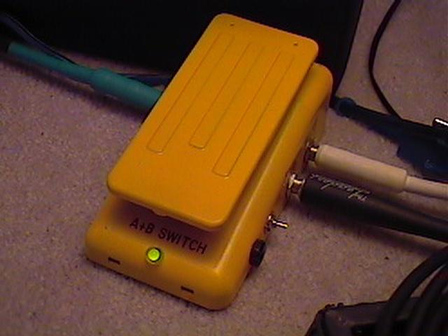 |
Here it is with the LED installed. I have it wired so that the SPST switch on the side cuts the power supply, which is a 9V battery. |
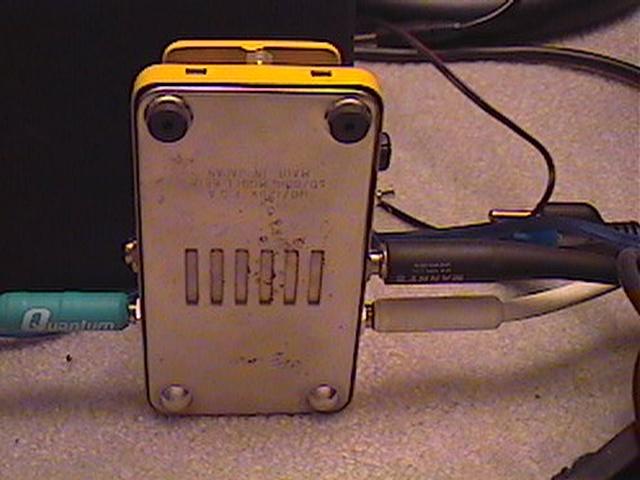 |
Here is a view of the bottom. To replace the battery, you remove one screw, and the bottom comes right off. |
This is very simple to make, and inexpensive. As far as the LED indicator is concerned, there are a couple of different ways to wire it. You can build a little circuit that uses the Millenium Bypass. The Millenium Bypass circuit only turns an LED off or on. My circuit is independent of the signal, and I have two colors, which is what I wanted. See links below for more information.