Building A "Volume Pedal De-Scratcher"
Last updated 09/23/04
After
being frustrated with my scratchy volume pedal, I decided to
build Craig Anderton's "Volume Pedal De-Scratcher". I
tried to avoid building this circuit by taking apart my sealed
pot (which showed no real signs of wear) and spraying contact
cleaner inside and cleaning it up very well. I also lubricated
all of the moving parts, too. (except the pot) Believe it or not,
just lubricating all of the moving parts does wonders. This stuff
all worked, for a while. To my dismay, it started being scratchy
again within a couple of months. I like to use volume swells a
lot, so this is a problem. So I figured that if a replacement pot
is around $25 + shipping, it would be advantageous to build this
circuit for around the same amount of money, and permanently get
rid of the problem. It's really not that much more of an effort to
build this circuit than it is to take your volume pedal apart and
clean or replace the pot.
The impetus for this project came about because I recently bought Craig Anderton's book, "DIY Projects For
Guitarists", and saw this schematic , which is exactly the
same one published in the original Guitar Player article
years ago. So I decided to "just do it".
The
circuit is pretty simple, just using a single opamp and a CA3080
OTA (Operational Transconductance Amplifier) opamp. I designed a PCB layout because I hate using perfboard. It's just
too messy and tedious for me, just as making a PCB can be
tedious. But, I like the finished product a lot better with a PCB.
And I find the assembly of a PCB is just a lot easier, as I don't
have to worry about getting all the connections right. It's
already done on my PCB layout, worked out beforehand. But you can
do the same thing with perfboard, too. There is also
a PCB layout which uses a TL072 at www.tonepad.com which has been
verified as functional.
Below is how I modified my Ernie Ball passive volume pedal. I believe this is the Model 6160 (?), which was likely made in the early part of the 90s.
I acquired it around 1997. In any case, it's the original pattern before all these different versions existed.
 |
Here is the basic assembly. I used a 1/4" piece of plywood to mount everything on, cut and shaped to fit snugly inside the volume pedal body using no screws or adhesive. Height is a limitation, so I kept the PCB as small as possible, 1.9"x1.6". I painted the wood flat black. |
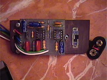 |
Here's a closer view. I drilled three holes on the left side for wires to pass through to the jacks, pot and battery clip/switch. I elected to use a SPST switch to turn off the power. I just don't like unplugging and plugging in cords all the time... I had to create a rectangular opening for the switch body, not as hard as it sounds - this is wood! Easy to work with. A piece of plexiglass would look cool, too. |
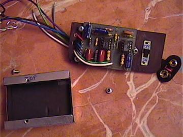 |
To avoid possible RFI or EMI problems, I decided to build a shielded enclosure for the PCB. It's simply just a piece of thin sheet aluminum cut to the appropriate size and bent as required. I used two small wood screws to fasten it to the plywood. I lined the inside of it with 1/16" self-adhesive neoprene sheet foam to avoid shorts. You can get an 8.5"x11" sheet of it from the crafts section at Walmart for 50 cents, and it comes in various colors. |
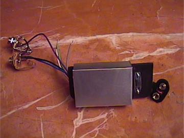 |
This is how it looks with the shield installed. The shield is about 2.25" wide, 1.625" high, and 0.75" deep. I also applied a protective coating on the back of the PCB to inhibit oxidation of the copper traces. Not really all that necessary, but this circuit is the most exposed to the environment than all of my other circuits, so it seemed like a good idea. |
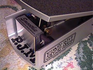 |
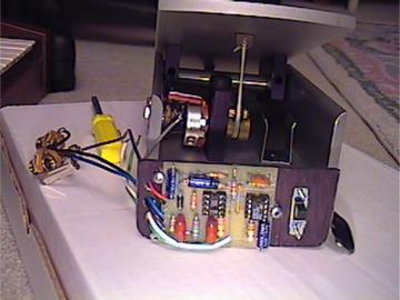
This is how it looks with the whole assembly installed in the volume pedal. A 9V battery sits in a battery clip behind the power switch, fastened to the body of the volume pedal with double sided adhesive tape. Connections to the pot and jacks are made with quick disconnect terminals. The whole assembly is very easily removed, and this mod is completely and very easily reversible, too. Getting your fingers in there is a bit of a pain, though. And, the jack nearest the block that holds the pot is a very tight fit... |
So, how about the performance? Well... now the scratchiness is gone! Noise level of circuit is pretty low, mostly dependent on what opamps are used. Even with a standard 741 opamp, it's a fairly quiet circuit, although there is a fair amount of white noise with a 741. A TL071 would be better. And better still is the TL051, which is twice as quiet as a TL071, but has higher THD (Total Harmonic Distortion) than the TL071. An OPA134 will work in this circuit with no tweaking required, but it does use a little more current than the aforementioned ICs. The NE5534 has virtually no THD, and is a pretty good all-around performer. I used the NE5534 in my circuit. If you find that your volume pedal has too much gain and is overdriving your amp, then try decreasing the value of R4 until the distortion is not present any more. As Anderton suggests, the easiest method is to install a 100K trimpot to dial it in exactly where you want it. This also gives you more flexibility to use the circuit with instruments of varying output levels.
Update 4/26/2024: Not too long after I created this page, I acquired the DOD FX-17 and forgot about this circuit. It was sitting in a drawer for 20 years and I decided
to revisit the project to see if I could improve on it. There were a few things that I wasn't quite happy with. One was the way that the Ernie Ball volume pedal is designed
with that string arrangement - it kept breaking on me. I finally got that part figured out, so string breakage is not so much an issue now. Second, the noise level when used with distortion was
unacceptably high - there was a lot of audible hiss. That was brought down dramatically by replacing the opamp I originally used with an OP134A (I don't remember what it
was as I took it out long ago). With that in place, the noise level is quite acceptable. I also added a 100K pot in series with a 1K resistor in R4 position. This
effectively creates a gain control, which elminates unwanted distortion and allows me to get consistent results with guitars that have widely varying output levels. Refer to the PCB layout and schematics linked at the top of this page for more info.
 |
In place of where the power switch was, I located the gain pot. This works out pretty well. There's just enough room to to put a knob on it, provided it meets certain parameters. Sometime after I initially created this webpage I added the 1/8" center positive power jack. I abandoned the use of a 9V battery as finding a stereo jack with an extra long barrel to fit thru the enclosure seems to be next to impossible and it's too easy to forget to turn off the power manually. |
 |
While I was at it, I rewired everything and used a much smaller gage wire (24 gage) as the 18 gage wire I had used originally was much too thick and stiff. It's all I had at the time, and finding the appropriate wire locally was not that easy (and still is not). Can you believe that I live in a city of 2,000,000 people and there is literally not even one electronics store here that sells wire and components?! When Fry's and Radio Shack went out of business, my ability to source anything locally went out the window. Anyway, the small black and white wires next to the CA3080 go to the gain pot (refer to the PCB layout and schematics linked at the top of this page for more info). |
 |
While I was at it, I replaced the original PEC 250K audio pot with a new manufacture Ernie Ball replacement pot. The new 250K audio pot was manufactured by Cosmos Japan. The reason I replaced it is because it had some kind of manufacturing defect which made sudden a rough transition at full CW position, and that just bothered me. Unfortunately, replacing the original pot meant that I had to solder the wires directly to the pot as the existing female spade connectors were a little too large for the lugs on the new pot - but now the action is smooth as butter! |
 |
One simple modification I also did was to add a post at the heel end of the treble to make the travel of the treadle shorter. With the new pot, there seems to be a different taper and the very long travel of the treadle becomes really unneccessary. Very simple to do using the factory rubber bumper with a taller screw in the original hole. This does not alter the appearance of the pedal and it's very easily reversible if I ever change my mind. The piece that elevates the bumper is a hollow tube with a flute on the end. I don't remember what these salvaged parts were from but it works perfectly for this. |
 |
This is how it looks when reassembled. I found a re-purposed knob which was just the right physical dimensions and the aluminum construction also
looks the part. I am happy that I revisited this project. This circuit is now what I had envisioned it could be. This was one of the first things I ever built (2004) and my knowledge and experience at the time was pretty limited. I've learned and done so much since then! I feel that this circuit is under-appreciated. It's a good solution in some cases. Yeah, I know, I could just go and buy a new Ernie Ball active volume pedal but the point of all this was to make a semi-failure from my early days of DIY into a success! |
