Troubleshooting the ART X-15 MIDI Footcontroller
Last
updated 8/30/05
By Paul Marossy
Although some of these units are over ten years old now, the SGX-2000 and the X-15 MIDI foot controller
are still some killer guitar effects units. This article will focus mainly on how I repaired my malfunctioning
X-15.
The main problem that I was having is that the up/down buttons and buttons 5 & 0 were not functional, but
were at one time. ART was kind of enough to send me schematics for both of these units, which helped tremendously. Identifying exact the source of the problem without a logic probe was, well, problematic. It was difficult to track down the source of the problem because in this circuit, everything is connected together one way or another and on top of that it's digital and I am used to analog circuits. In spite of that, with some help from people at several different forums, I figured out the most likely suspects and decided to focus on that and go from there. After studying the schematic for a while, it appeared that the IC chips labeled "U6" & "U9" may be faulty. U6 & U9 are a 74HC244, and that is a CMOS Octal 3-State Buffer which controls what the little footswitches under the pads do. I decided to replace both of these chips since they both shared inputs from the footswitches. So, armed with this information, I went down to the local electronics store and
bought two new 74HC244 chips & some IC sockets to replace the existing IC chips. After cutting out the existing chips,
desoldering the cut pins and soldering the IC sockets into place, I popped the IC chips in the sockets and powered
up both units. To my surprise and great joy, everything was working exactly as it should be! And the parts required only cost about $5 total.
What made the chip(s) go bad, I can only surmise, but my guess is that it was probably due to repeated exposure to static
electricity. IC chips in general are very sensitive to static electricity and can get damaged by exposure to it over a period of time. The reason why this is happens in a CMOS device is this: When a voltage spike caused by a discharge of static electricity hits the chip, the chip input is pulled to whatever that polarity may be and that spike is only limited by the on-chip protection. The on-chip protection is a silicon resistor in series and parasitic diodes from along the body of that resistor to chip ground or +V. The chip "ground" is a metallization layer that's 20ma thick as is +V layer. From there, it has to get to ppower supply +V and ground, and it does this through the IC pins and the PCB, which are about two to many amperes thick. There's a certain chance that spikes will eat away some of the 20ma metal on the chip with each spike.
The X-15 seems to have little to safeguard the IC chips in it from this sort of damage. There is way to do a mod to make it more protected from this kind of damage, which is detailed at the bottom of this page. Installing IC sockets is the less invasive and easier method to deal with possible future problems. Below are some details on the unit and parts that had to be replaced.
 |
This is what the foot controller looks like. This is the original X-15 unit that was introduced into the market place. It was made in 1991-1992. |
 |
This is what the original SGX-2000 looks like. It can be upgraded to an SGX-2000 Express by changing out one IC chip inside. |
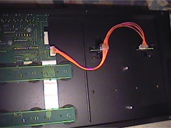 |
There are a total of six PCBs inside the unit. There is the main PCB, one for the LED display, two for the footswitches and one for each foot pedal. The foot pedals are attached to the main PCB by jumper wires. Each PCB is connected to the main PCB by wire ribbons. |
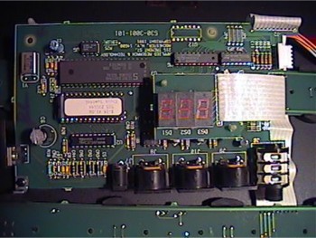 |
This is the main PCB where the 74HC244 chips can be found and are labeled U6 & U9. U1 is a EPROM chip, U2 is a SOIC Octal "D Latch", U3 is an 8-bit microcontroller, U4 is a standard logic IC, U5 is a serial access EEPROM chip, U7 is a logic gate and U8 is an photocoupler. |
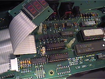 |
To get to U6 & U9, you have to carefully pull the LED display off of the plastic posts so you can have full access to the chips. I cut the pins to the chips with some wire cutters and then used some desoldering braid to carefully remove the old pins and solder. It's a little difficult to get all of the solder off of the PCB because it's double sided, but with a little patience, the job was done in about 25 minutes. Note: You have to be careful when desoldering components from a PCB so that you don't overheat the PCB and damage it in the process. |
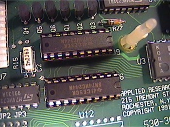 |
And here are the new chips installed in the IC sockets. This way, if the chips ever go bad again, replacing them would be a 15 minute operation. |
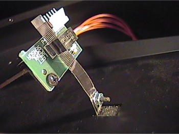 |
While I had the foot controller apart, I thought I would take a closer look at the the foot pedal PCBs. The foot pedal uses a "quadrature encoder" strip (which is similar to what non-optical mice use to sense relative position) and a position sensor. Moving the foot pedal up/down moves the strip thru the sensor and changes parameters inside the SGX-2000 according to how it is programmed to respond to the sensor. |
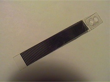 |
This is what the encoder strip looks like when removed from the foot pedal. |
To prevent this from happening again, there is a mod that can be done to protect the circuitry
from becoming damaged from repeated exposure to static electricity. At the inputs that go off to the pushbuttons
(Pins 2, 4, 15 & 17 of U6), install a series 10K resistor and a diode from ground to pin and pin to +5.
Arrange the diodes so they're reverse biased normally. That way, a transient riding in on the
KSCAN line will move the outside end of the 10K to above/below the power supply, a diode
will conduct, and the excess energy is eaten by the 10K and the power supply, which is where
the energy is dumped. (Thanks RG Keen!)
The thing that bugs me about all of this is that you would think the designers would have
done a better job at protecting the circuit from this kind of damage, but it seems that they
were too cheap to put in four more resistors and eight more diodes. Or, they felt that the
zener diode/transistor power regulator arrangement would be sufficient, which in practice isn't
always.
If you ever find yourself with a malfunctioning X-15 foot controller, I hope this page helps!