The Seymour Duncan Convertible 60 watt Tube Amp
Last
Created 02/26/05
Last updated 09/04/08
By Paul J. Marossy
There is a terrible
lack of any information on the web on this particular amp, so I decided to make
a webpage for this amp which has been out of production for many years
now. So far, all inquiries about this amp from
people writing to me have been in Europe, so it seems like this was a popular
amp there or there just is a serious lack of info on this amp. This page is in its
infancy, but I have put together what information I have on this amp so far. Many
who have written to me about this 60 watt amp really like it.
The 60 watt model was a combo amp similar to the 100 watt model, but without
the variable wattage circuit of the 100 watt model, a solid state rectifier
and it also used only two preamp modules versus the five modules that the 100 watt model
used. The overall construction
of the 60 watt model is different than the 100 watt model in several ways -
the PCB appears to have been manufactured differently (or by a different manufacturer),
the phase inverter tube is internally mounted, the preamp modules lay on their back as
opposed to the vertical mounting of the 100 watt model and the pair of EL34 power tubes
are horizontally mounted instead of vertically as in the 100 watt model.
Matt Farrow of Pharoah Amps was kind enough to provide a schematic for the power amp
section and a technical analysis of this interesting amp. The following is extracted
from emails that he sent me.
"The Seymour Duncan Convertible 60 is a unique amplifier - it shares some common
design elements with the Convertible 100 (EL-34 output tubes, preamp modules, footswitching
capability,) but it also has a lot of unique features.
PREAMP
The C60 uses a FET-based preamp design before the two preamp module stages. The preamp
design is very similar to the Hot Mod module, which is supposed to be fairly rare on the
C100's. The first FET is a J230, a small-signal device, and is direct coupled to the
second FET, a BUZ42. This design gives a very high input impedance (around 1 megohm), and
has a lot of available gain. The FET preamp feeds a pair of voltage divider controls
(Overdrive Red and Overdrive Green,) which in turn feed the inputs of the tube modules.
TUBE MODULES
The modules are interchangeable with the modules on the C100, and to my knowledge,
no new modules were produced when the C60 was introduced. My personal C60 had Classic and
Classic Distortion modules in place when I purchased it, but the amp will work with any
of the available modules.
The module sockets carry 10.3VDC regulated (for the tube heaters or power supply for some
of the IC modules,) as well as a filtered unregulated DC voltage on pin 6 (output.) This
DC voltage is to power the tube plates, and the signal is capacitively coupled to the
next amplifier stages by C35 and C36 (0.1uf / 630V.) Any solid-state modules (with the
exception of the FET module) should have a their own coupling capacitors, otherwise
several hundred volts DC will be applied to the module output.
CHANNEL SWITCHING
The C60 uses a small-signal relay to switch channels. Each module output is connected by a
coupling capacitor (mentioned above) to its repective Volume control. When the relay switches,
the unused channel volume control is shorted to ground through the relay. This arrangement
helps to prevent popping when switching channels. An interesting note - the channel switching
section uses resistors to "mix" the signals coming from the Volume controls, and the resistors
are of unequal values. The Red module thus presents a slightly hotter signal to the next
stages than the Green module, even if the two modules are the same.
REVERB
The reverb is a very standard design, using an LM380 op-amp to drive a spring tank. The LM380
is capable of running from a single supply, and should only be replaced with another LM380
should the reverb circuit fail. The reverb output is amplified with a TL082 FET input op-amp,
and returns to the signal chain after passing through the Reverb control.
EQ
Unlike the tone stacks on the C100 which can only cut, the C60 has an active EQ which can cut
or boost (supposedly up to 15dB...) The EQ section uses an interesting circuit called a
gyrator to acheive its filtering. The gyrator EQ is very common in guitar devices, including
the Boss GE-7 and HM-2 / HM-3 pedals. Most Boss pedals that have any kind of active EQ use
gyrators. The actual EQ circuit is almost identical to that of the EQ section of the Classic
EQ and High-Gain EQ modules, although the C60's EQ is only 3 bands instead of 4. The C60's
filter frequencies are also tweaked to work with the amp, which seems to be voiced a little
more towards the bass than the C100.
PHASE INVERTER
The C60 has a standard long-tailed pair phase inverter, similar to many Fender and Marshall
designs. The C60 takes its negative feedback from the unused 16ohm tap off the output
transformer. The C60 also uses a bias balance control to help correct any mismatch in the
output tubes, although its overall bias is not adjustable.
POWER AMP
The C60 uses two EL34 tubes in fixed bias, class AB for its power section. The C60 lacks the
triode / pentode switch on the C100, but it does use the same ultra-linear output stage
design. This design makes the power amp very clean while retaining dynamics.
POWER SUPPLY
The Convertible 60 lacks the tube rectifier of its bigger brother, instead using a solid-state
full wave rectifier design to save chassis space and weight. The board has a provision for
using a voltage-doubler power supply, presumably Seymour Duncan thought that they might have
to use a different type of power transformer. Additional mounting holes are also present on
the chassis, perhaps to accommodate this type of transformer.
HOW DOES IT COMPARE?
The C60 is almost as loud as the C100, but lacks a bit of the complexity of tone. The
solid-state EQ section is very versatile, much more so than the passive tone stacks on
both channels of the C100. The best comparison I can make to the C100 is to say this -
Set up your C100 with the following modules: Hot Mod, Classic, Classic EQ. That's what
the Green channel is like on my C60. For the Red channel, replace the Classic module with
the Classic Distortion module. The front end is a bit harder sounding, but with some tube
character."
Below are some pictures of the 60 watt model sent to me by some readers.
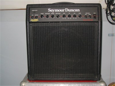 |
Here is a view of the front of the amp. It's very similar in appearance to the 100 watt model but with only one row of controls. |
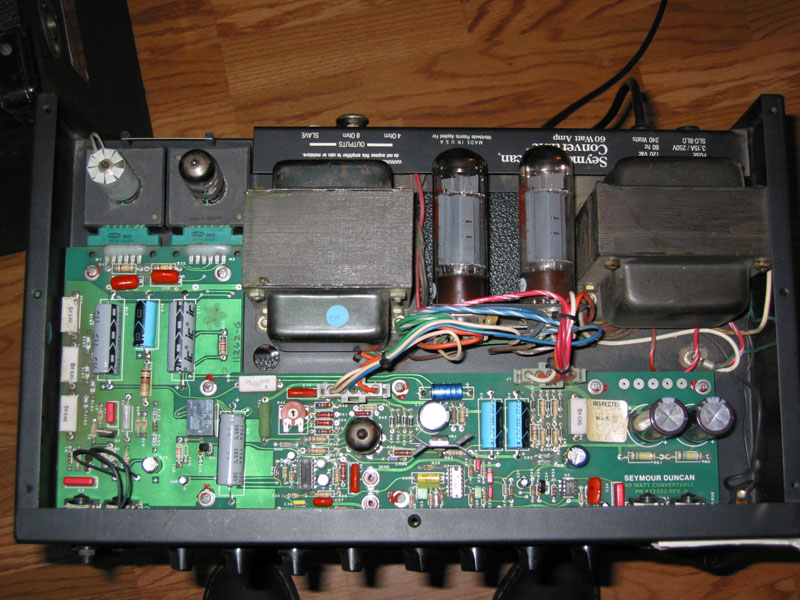 |
Here is a view of the chassis. The general layout is quite different than the 100 watt model. Notice the horizontally mounted power tubes between the power and output transformers. |
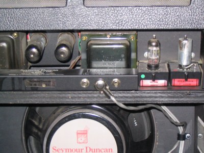 |
Here is a view of the chassis from the rear. |
Here's an update: I received a few emails lately asking whether R4 adjusts the gain of the input FET, which I couldn't answer with 100% certainty. Since I don't own this model, a Convertible 60 owner has verified for me that R4 does indeed control the gain of the input FET - thank you!
Added 9/4/08: Some additional information from Tom Addy (UK) concerning measured votages and what appears to be an error on the schematic. 60 Watt Convertible Preamp Schematic (1.3Meg) 60 Watt Convertible Power Amp Schematic (632kb)
"Center tap on Output transformer (J1-1) = 510V, A = 503V, C = 478V -- but this may be pulled down a little (to around 470V) if you have two preamp modules connected that use the C voltage supply for preamp anodes (e.g. Hi Gain, Presence.), B = depends on which preamp modules are connected but can be 408V (with 2 modules that use B anode supply), 434V (with one B supply and one C supply) or higher with two modules that use the C supply. Note that 'Classic Distortion' uses the B supply but doesn't seem to pull the B voltage down much. D = 42V (set at a constant by the two zener diodes CR19 and CR18 (18V and 24V respectively), E = -62.5V (EL34 bias voltage supply), G = 10.5V (pre amp heater), I or '-V' = -35V (used for the various EQ/reverb integrated circuits). '1/2-V' is just over half at -19V, J2-5 and J2-4 which supply the EL34 heaters are at 8.4V.
Remember to understand the voltage drops in the chain from the center tap to D, it is important to realise that R53/C11 and hence the 'B' supply is not part of the chain, but rather a branch stemming from the junction between R54 and R48. So the voltage chain is effectively: center tap to A to C to D (dropping from 510 to 42V), with B as an offshoot. So unless my amp is a freak (or maybe a UK variant???) the preamp schematic is slightly wrong in this respect!"
Click Here for a JPG diagram of the corrected version of this area of the schematic drawn by Tom.
If you have any other information
to contribute, please send me an email
!