Seeing The High Resistance Ground
Paul
Marossy
Original Article by Wm. H. H. Wilkinson 1962
How high is a "high resistance ground"? It might be just a fraction of an ohm. And even that much can be too high where zero resistance is a must.
Measuring fractions of an ohm is just about impossible without the right instruments, so high resistance trouble is often checked out by hopefully reflowing all suspected solder joints or by searching for the the bad joint with a short jumper whose resistance may be higher than that of the bad joint!
There is a simple way to look for the trouble and to see it - literally. Just give the unwanted "piece" of an ohm a controlled chance to differentiate a square wave as you watch the action on your scope. The basic differentiator circuit is shown in Fig 1 below.
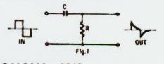
Select C and the frequency of the square wave input so that a value of R less than 1 ohm will give a short time constant. One cycle of 100-kc input requires 10 microseconds, and the width of the square wave's top, therefore, is five time the 1 microsecond constant.
Now, all that remains to be done is to connect the scope, square wave generator and C so that the high resistance ground can be inserted in the test circuit without the burden of unwanted resistance such as the fraction of an ohm in every good test lead. Figure 2 below shows how this is done.
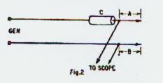
Probes A and B (Fig 2), if ideal, would have zero length and zero resistance. Impractical to
accomplish, but they can be kept sufficiently short. For Probe A, cut one lead of the capacitor as
short as possible, leaving just enough to tack on one side of the scope leads. For Probe B,
use a piece of heavy bus wire, or simply tack the generator lead to the tip of the scope's
direct probe. This way, the scope sees only the potential change across whatever resistance may be
placed between the probe tips.
1. Select a square wave frequency and value of capacitance so that time constant is about 1/10
of one cycle (T=RC=0.1*1/freq).
2. Construct probes to assure zero resistance: From C to one probe tip-connect one scope lead to this tip.
(A in Fig 2) and from tip of other to junction with other scope lead (B in Fig 2)
3. Adjust generator and scope for a stable square wave pattern while the probes are seperated. Use
the least sensitive position of the scope's vertical attenuator that will permit trace amplitude
to fill the screen.
4. Now touch probes together and examine the display. Zero resistance shorts out the square wave -
the trace drops to a straight line. Any resistance at all will differentiate the
square wave and produce the typical spikes. Increase sensitivity of scope input and
examine again (be sure to reduce sensitivity again before seperating probes). This step
establishes a reference pattern. Resistance in the probes and setting of vertical gain
controls will determine whether it is a "pure" straight line, or one with tiny spikes at
the square wave frequency. Be sure to check sync - the sharp drop in trace amplitude may require a slight adjustment
of the sweep controls.
5. The test circuit is ready. Adjust controls as in step 3, then touch probes across suspected joint.
Straight line? The joint is "clean". Spikes? There's a high resistance ground. Square wave with overshoot?
Means long R-C, hence a very high resistance.
It is possible to detect resistance as low as .02 ohms using clip leads and a capacitor. Hopefully, high resistance ground troubles will never come your way, but if you suspect that it is there... try seeing it.