The Allan Holdsworth Harness
By Paul Marossy
Created 11/21/23
Updated 1/41/24
The Harness is a very interesting device. I don't know how many of these Allan made, but it may be somewhere around 75-100 units between the different standard versions offered & customized units. If you have one of these and want to help me generate a verified schematic, please
contact me via the email on my home page!
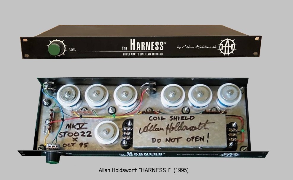
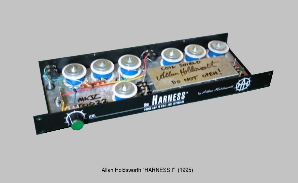
Here is an example that was made in 1995. It's the simple version with just one knob - a level control. This one is confirmed to be a Harness Version I. It
appears to have the same basic components as the 1994 example above minus three of the controls on the front panel, and the toggle switches. The Harness and the Harness II were marketed under the Sonic Tools brand name. They utilized professionally made enclosures with cool silkscreened graphics, and Allan wired them.
In this same 1995 example below we can see the coils, which Allan called chokes, with some sort of blue tape (transformer tape?) covering the windings. On one of his test units he calls them "1mH chokes". These "chokes" are likely air core inductors made with approx. 18-20 AWG copper wire. Without having a Harness in hand I can't 100% determine the exact characteristics of these chokes. On this
"Test Unit #2" you can see he had the option to switch every "choke" in or out of circuit. The standard Harness has no switching options.
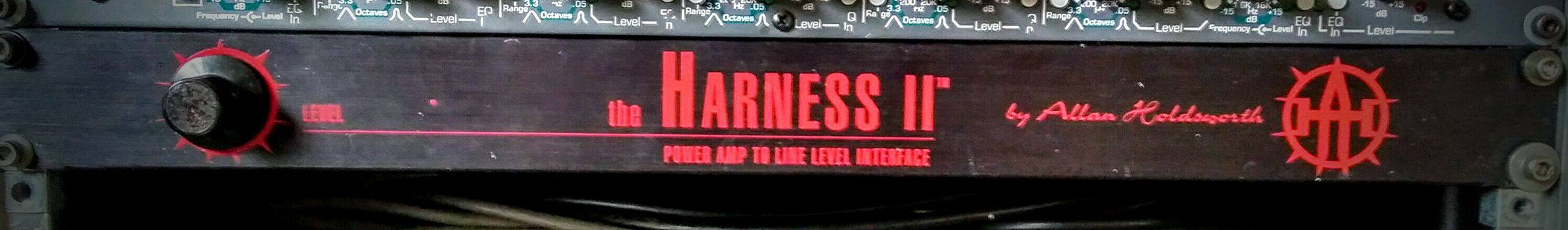
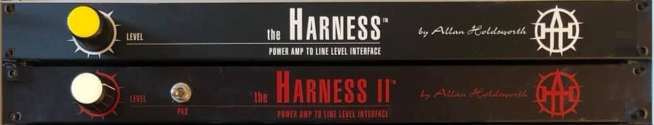
Here is an example of a Harness II. Unfortunately we can't see the inside of this one. The red graphics
makes it immediately recognizable as a Harness II. Allan has been quoted as saying he felt that the Harness II was the best version. I have seen the inside of one of these
units and it is considerably different than the Harness I version. My understanding is that only 20 examples of this version were made.
Here is another example of a Harness II. This is one of only a few that had a pad switch.
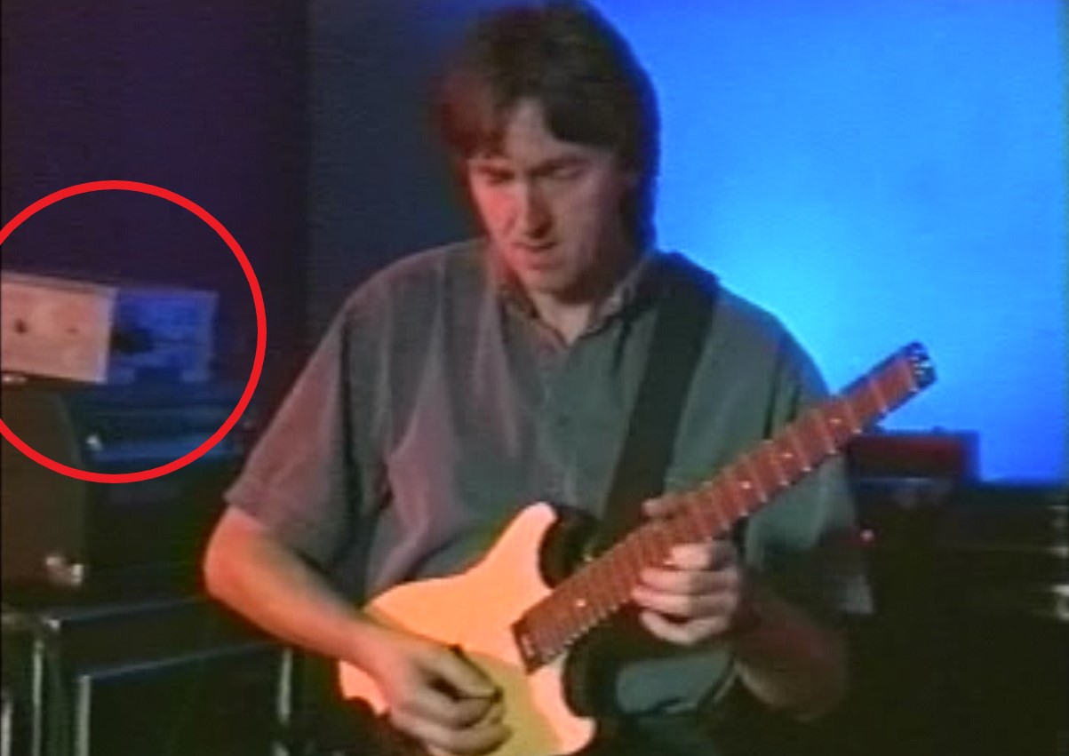
Interestingly, in the 1992 REH instructional video, it appears that one of Allan's original harness units (there were several versions) is sitting on top of the amp head.
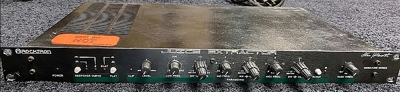
In this 1990 picture we can see Allan with a similar looking box to the one in the REH video sitting on top of a naked guitar amp chassis (Burman Pro 501). He called this device the "Juice Extractor", as evidenced by the name written on the front of it with permanent marker. It appears that he had to call his own hand made units The Harness because Rocktron was concurrently making their version of the Juice Extractor at the time. Here Allan is taking the output from the Burman Pro 501 and feeding it into the input of the Juice Extractor, the output of which is going to a Pearce G1 preamp. This in turn was routed to Roland SDE3000s for stereo delay.
In this 1991 picture we can see Allan performing with this same Juice Extractor box on top of his Mesa Boogie head which is on top of his large racks containing eight delay units, parametric EQ and a host of other things. It's an interesting coincidence that the time period of the early 90s is when many Holdsworth-ians feel that he had his best "tone".
Sometime around 1989 Rocktron offered their version of the Juice Extractor (aka Harness), manufactured "under license". Word on the street is that Allan got screwed by Rocktron - he had no control over what they did with his circuit and he also did not receive any profits from it. Allan ended up breaking his contract over a disagreement. Anyway, the only thing that the Rocktron Juice Extractor and Allan's hand built Juice Extractors had in common was the name, the concept behind the product and an association with Holdsworth's name.
It appears that Holdsworth was continually tweaking the Harness/Juice Extractor concept, possibly even as late as 2013. You can see Allan's crazy "super harness" in THIS VIDEO.
These mysterious rack mounted reactive load units have intrigued me since I first saw one up for sale in 2007. The more I dug into the history of this device, the more interesting and convoluted the story became.The idea behind this box is
to take the speaker output of an amplifier and knock it down to line level so that you could in theory silently take advantage of power tube distortion without
needing to have an extremely loud amp. You could then route the output of this box to the input of a stereo processor and so on. Allan hated the sound of
preamp tube distortion, and I am with him on that. It's nasty sounding to my ears as well. One thing that is unique to The Harness is the ability to take advantage of transformer saturation, which other devices cannot quite replicate.
I've been trying to round up a schematic for this curious creation for a long time but have not had any success thus far. It appears to
be a passive RL circuit (no power required) which utlilizes some hand wound inductors and what look like electric resistance heater elements. In fact, they are heating elements. In Allan's own words:
"It was basically a Nichrome wire, which is a heating element, and that's what I used for the load, and for some reason because it has an inductance thing going for it, as opposed to a fixed resistor, they just don't sound the same, just really liked that so I just bought miles and miles of his heater coil from this company in Alabama."
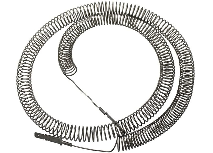
At left is an example of a nichrome heating element. This one is capable of handling 4.6kW (4,600 watts).
A guitar amplifier output needs to see a load as close as possible in characteristic to the rather complex impedance signature that a guitar amp speaker has. This is no small feat.
The guitar speaker is not a mere coil wrapped around a bar of iron. There is an existent and independent magnetic field at play, meaning that coil is shooting signal back
to the amplifier output in answer to the one it receives. To add that, to there are the "ballistics" of the moving parts of the speaker as well. Let's also not forget about the acoustics of the speaker cone, its baffling and the surrounding space. This is perhaps a minor issue when the amplifier output stage is operating within its linear characteristic, and the waveform of the signal is relatively simple and of one frequency. But when it is driven into non-linear portions of its curve, and more complex
waveforms and multiple frequencies are added in, then the math becomes exponentially more complex. And coming up with a surrogate load design can become a tall order indeed.
Fortunately The Harness is not a speaker simulator nor is it an attentuator, and it cannot drive a speaker directly. There is no EQ on the "standard" units.
The Harness Version I is best used with more modern (high gain & master volume) type amps like Boogie, Soldano, etc. The Harness Version II was designed for "Vintage" non-master volume amps, like older Marshall and Fender amps. The Harness takes the place of the guitar speaker and silently converts a guitar amp speaker output to a line level output with level control. It's meant to be used with an 8 ohm to 16 ohm speaker output impedance from the guitar amp. It should be used with care for the amp in mind. Allan typically would output the Harness into a parametric equalizer and then split to multiple direct outputs for mixing the direct guitar amp signal with various delay line signals. These are rack mounted, single space units that weigh about 8 lbs. Frequency response is 10-40 kHz. Input impedance is stated as being 8 ohms. Output impedance is 130k ohms. Power handling is 100 watts.
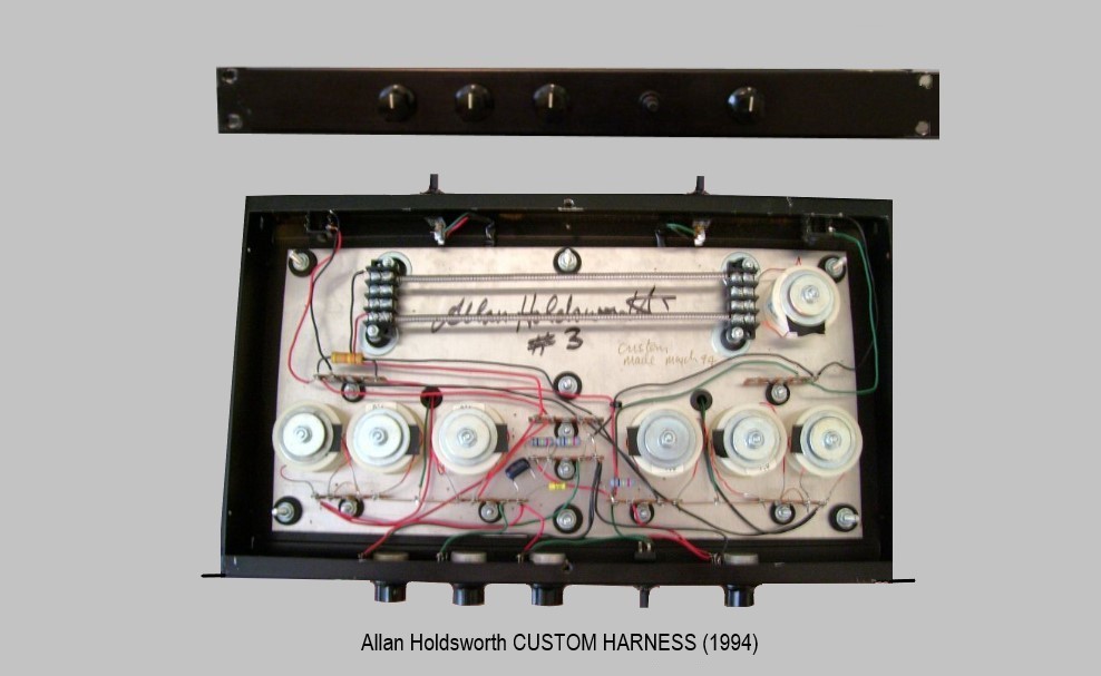
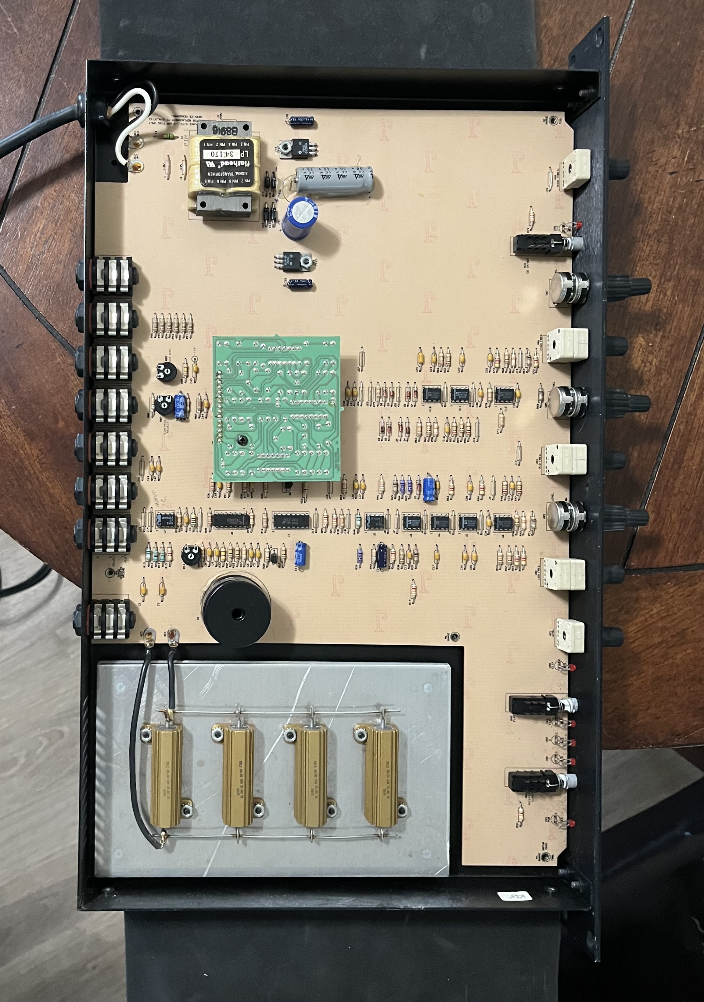
Below is a "custom" version which was made in 1994. It appears that two of these switches can remove certain coils from the circuit. I'm guessing that's to make it suitable for either a master volume amp or a non-master volume amp. Two of those knobs appear to be a simple low / high EQ, and two are level controls. The switch on the front panel appears to
select between the EQ section and a straight output. I traced this one out and made a chassis layout & schematic for it. CLICK HERE to view. Observe the general layout and components and compare with another standard production example below.

.jpg)
The Rocktron circuit is pretty much completely different than Allan's simple passive circuit and they just didn't sound as good, according to Allan. My understanding is that this was due to the use of almost a purely resistive load with one 1mH inductor vs. the inductive reactive load with nichrome heater elements, as designed by Allan. It appears they had to make that change due to a patent held by Groovetube at the time (need verification on that). Rocktron apparently discontinued the Juice Extractor because people didn't know how to properly use it and were "blowing up amps" as a result, by "turning everything up to 11". The output transformer certainly is at risk of being damaged if this is used incorrectly. You can get an idea of the circuit by viewing the mostly complete but very poor quality schematic HERE.
In this unit there are four 31.6 ohm 50 watt Dale resistors in parallel for a 7.9 ohm load with 200 watts power handling capacity. They are attached to an aluminum heat sink which is 1/2" thick. The rest of the circuit is dual or quad opamps with the "hush" circuit on a small daughter board which contains two quad opamps and a dual OTA (dual operational transconductance ampflifier). They operate on a +15V/-15V bipolar power supply.
That's all the information I have on these units at the moment. I hope one day in the future to finally crack one of these and generate a 100% verified schematic.
May be wishful thinking but that's my hope! It was most interesting modeling this design in LTSpice (see links below). I suppose today this is kind of an
outdated idea with all the speaker emulation software and attenuator devices currently available but at the time when Allan was making these, modeling software/amp modelers still sounded terrible
and unconvincing. A lot has changed since the mid-90s! In any case, I still find these units very interesting. I can imagine Allan building these in his basement and
pondering Nicola Tesla's achievements while writing tunes for the Wardenclyffe Tower album. He seemed to be something of a genius himself.