Converting 5-PIN DIN Jacks to 1/4" Jacks
Last updated 06/17/26
By Paul Marossy
To date I've had to convert six late 1970s / early 1980s Soviet-era guitar effects to 1/4" jacks. It used to be very confusing, but after looking at a lot of
positive ground Soviet-era guitar effect schematics (most 9V battery circuits in this time period were positive ground), and making this conversion myself a few times over the last three years, I've discovered there is a
convention to how these 5-pin DIN input and output jacks are wired. What used to confuse me the most is the power switching scheme, but now that I understand it, it's
not really that complicated. The object of this webpage is to help others that want to make this conversion as well, because using crappy adapters that don't
pass a signal or don't have the correct connections inside can be very frustrating, and well because it's just impractical to use these with already bulky guitar pedals. Note
that devices which are not powered by 9V batteries may be wired differently, so consult the schematic if one is available.
So what is the wiring convention? It's really pretty simple. On the input jack, Pins 1 & 3 are very often connected together or it's just Pin 1 that is connected. In some cases,
Pin 1 will be straight in and Pin 3 will be going thru a resistor to the input of the circuit. These are the signal. Pin 2 is the ground, and very often the tab which is connected to the metal case is also connected to Pin 2. This provides the path for the metal enclosure to be grounded as well. Pins 4 & 5 will be left unconnected. Note that it is NOT the input jack which switches the power.
The output jack is a little more complicated. As with the input jack, Pin 1 is the signal. Pin 2 is ground, and the metal case of the 5-pin jack is usually connected to this
pin as well. Pin 3 is usually left unconnected. Pins 4 & 5 are what switch the power on when a cable is inserted into the jack. Pin 4 is typically connected to the negative
side of the circuit and Pin 5 is what is connected to the 9V battery's negative terminal on the "battery snap". The positive terminal of the 9V battery is ground, and is
also typically connected to the chassis ground. When the pedal was new, it was usually supplied with a cable that made sure the connections were correct for the pedal as there were
cables that were wired in various other ways. These OEM cables had Pins 4 & 5 connected internally, so that when the cable was inserted it would switch the battery on.
In the graphic below we can see how the pins on the 5-pin DIN jack are arranged, and where the equivalent connections would be on a 1/4" mono jack and a 1/4" stereo jack. The trick is wiring the output jack. At this point you could re-wire it so that the input jack is what switches the power on but I prefer to just leave it the way it was designed. The INPUT jack is simple. The wires from Pins 1 and/or 3 go the tip connection of the jack. Pin 2 goes to the sleeve and you're done with that part. On the OUTPUT jack, Pin 1 goes to the tip of a stereo jack, and Pin 2 goes to the sleeve. The wires that were previously connected to Pins 4 & 5 get connected together (make sure you protect the bare wires). Remove the wire that was connected to the positive terminal of the 9V "battery snap" and run a new wire from there to the ring connection on the stereo jack. If you've done everything correctly, you'll now have a much easier to use guitar pedal!

The other matter to address is how to make a 1/4" jack work where the 5-pin DIN jack was previously. I've seen several ways how people deal with this but in my opinion they all look like crap. Personally, I like to make adapter plates out of about 1.5 mm or so thick aluminum, which allows me to insert the whole assembly into the existing holes in the enclosure and fasten them with the existing screws. The aluminum is very easy to work with and strong enough to do the job. One some pedals it is a real fiddly hassle to get these little nuts & washers back onto the screws but it can be done with some time and patience. The Kazan pedals were the most difficult ones to do as they have a lip on the enclosure which makes it a lot more difficult.
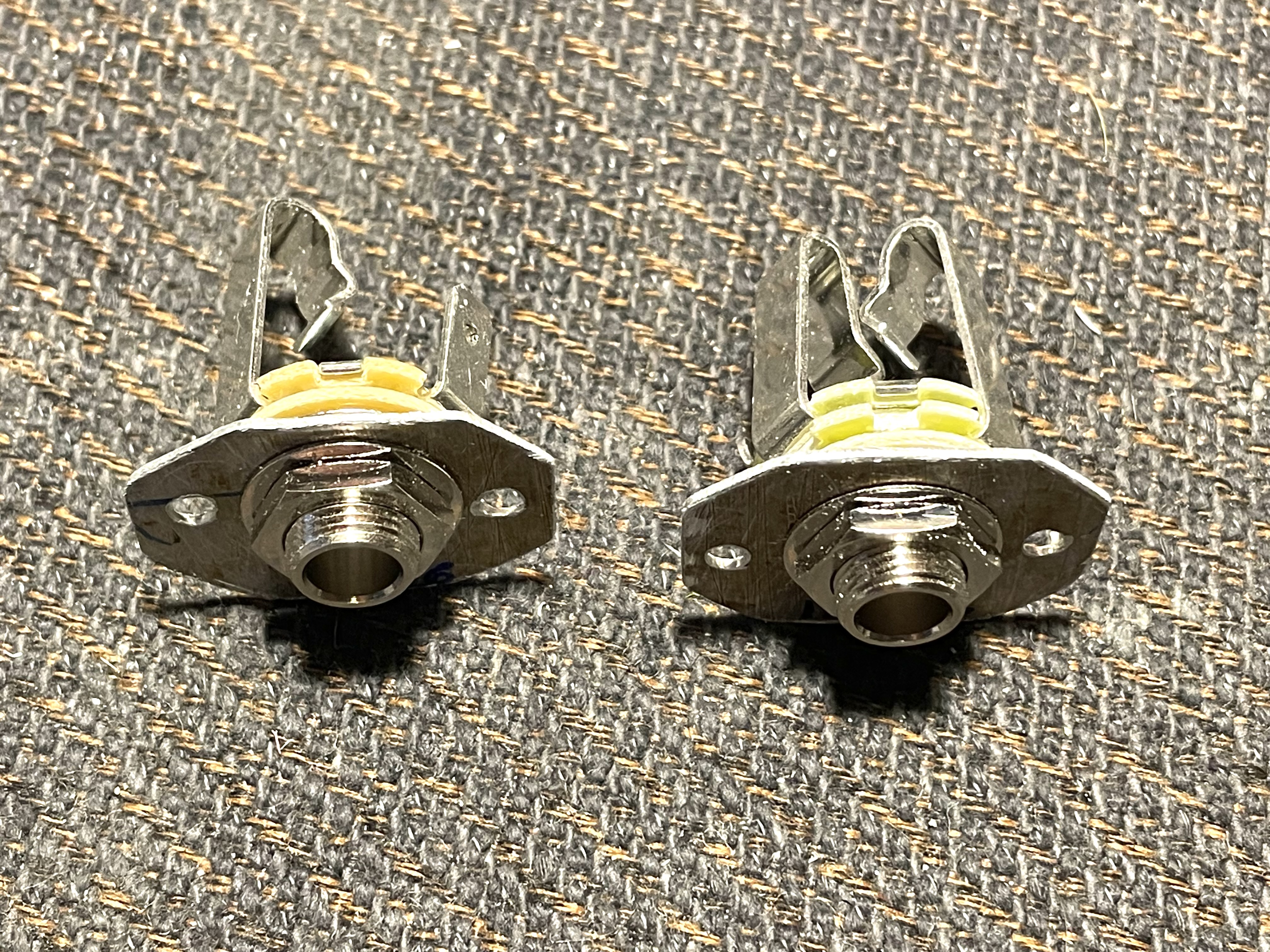
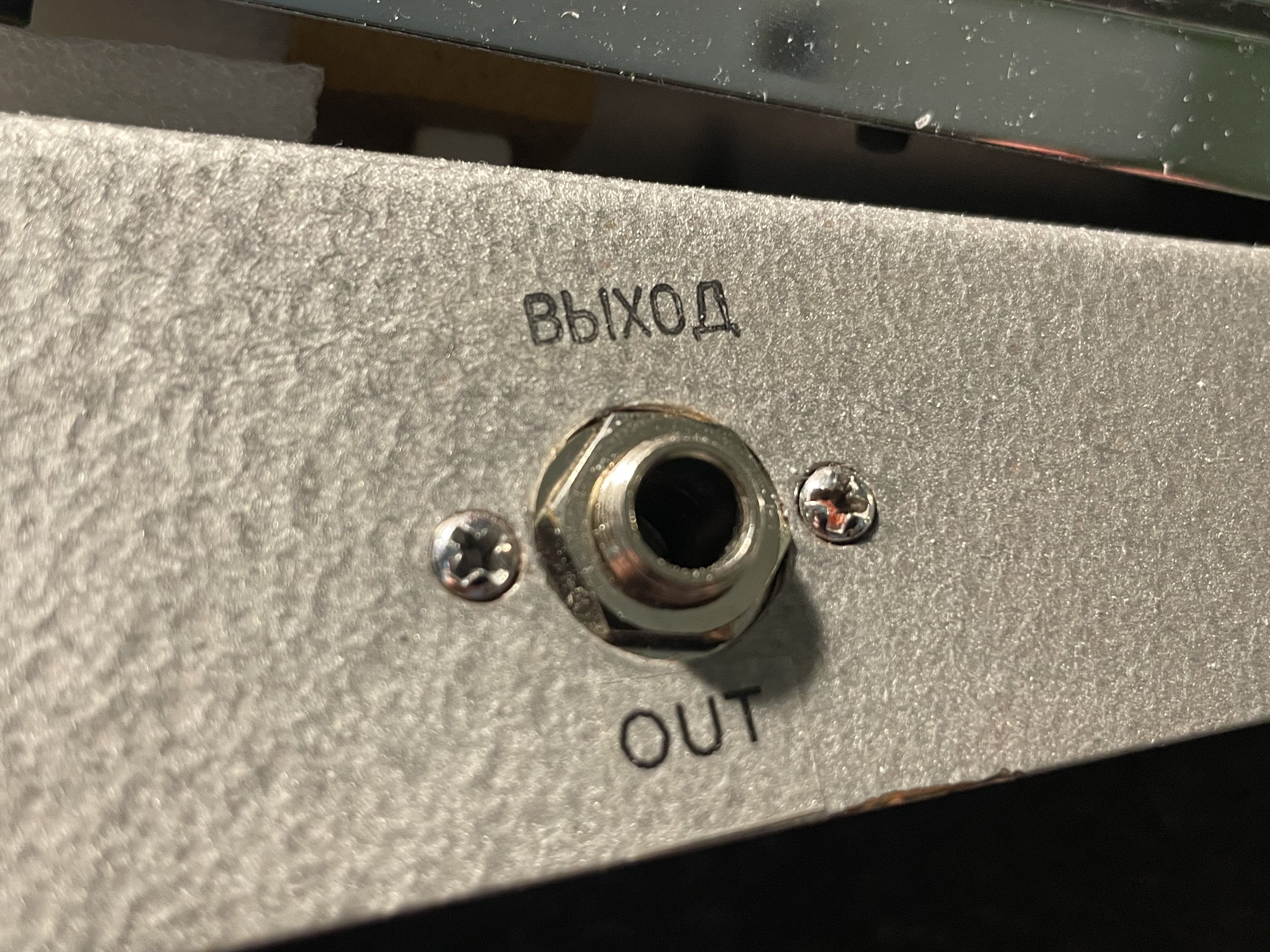
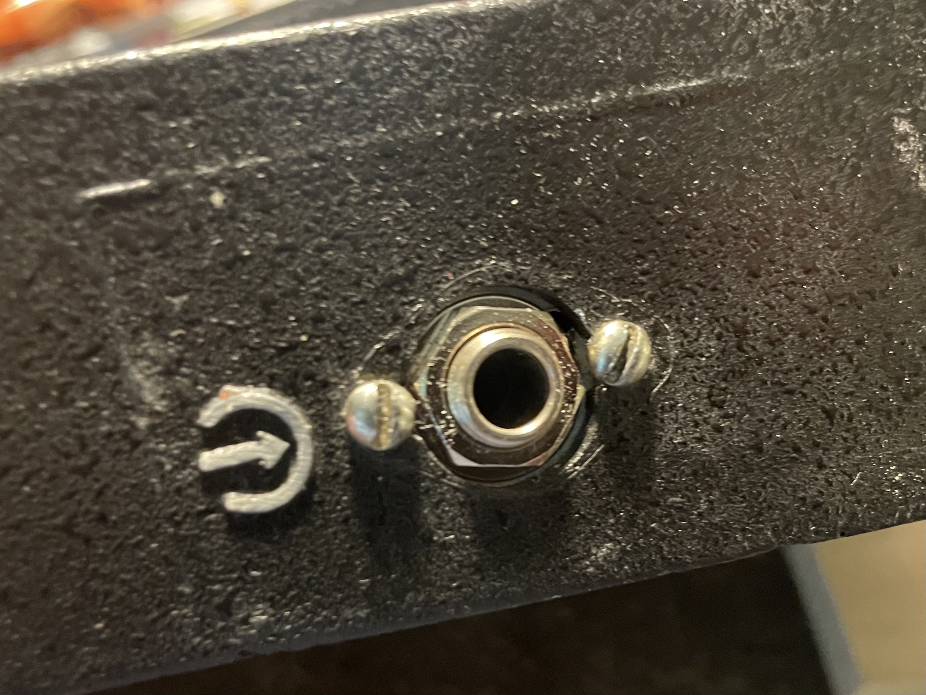
Below are two examples of my most recent conversions. That is in my opinion the cleanest look I can achieve without leaving small holes in the enclosure, using some huge ugly washers or by using some other unsightly method. These little adapter plates are plenty strong enough to do the job too, as well as leaving the chassis grounding scheme intact. I have used plastic jacks on one conversion, just because that's all I had at the time. I just made sure the chassis was grounded too since the plastic jacks are isolated from the enclosure.
So far I've been able to convert all of my Soviet-era guitar pedals to 1/4" jacks except for one - the "Spektr-1". There is just not the physical room to make this conversion to 1/4" jacks. But it's a weirdo anyway, so in that case I made a whole customized arrangement to use it with standard 1/4" cables via custom wired cables connected to 1/4" jacks attached to a wooden base.