My "Bulldog" Tube Overdrive Pedal
AKA "The Shaka Tube Chronicles"
Last
updated 3/5/04
By Paul Marossy
This is one of Aron Nelson's latest creations: the Shaka Tube. I renamed it the "Bulldog". It uses half of a TL072 type dual opamp, the output of which is fed into a 12AX7 preamp tube. The schematic can be found at http://www.diystompboxes.com in the schematics section. This one was a little bit more complicated than I thought it would be before I started building it. I created my own PCB layouts from looking at the schematic, since at the time I decided to build it, there were no PCB layouts available for it. It just never quite sounded quite right to me, at least not like the sound clips that I have heard. It had been sitting in my closet for nearly a year. So, I have rebuilt this pedal since this page was originally published. Pertinent new information is in red, and some stuff has been deleted all together.
Below is some more details and pictures of this project.
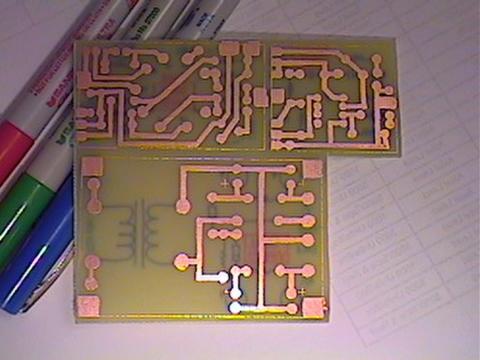 |
Here is the PCB just after etching. I did three boards at once, since that is what this circuit requires due to its complexity. (The circuit isn't that complicated, but the physical layout of everything is) This PCB layout got trashed, it had a mistake in it somewhere that I couldn't figure out. I used perfboard to rebuild the entire circuit, including the tube socket, and I still had to use three boards for the new circuitry. |
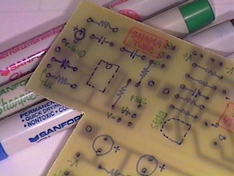 |
I like to use a fine point Sharpie to mark where each of the components goes before drilling and cutting the boards. This makes assembly a lot easier and faster. I still use this same method when I use PCBs to build a circuit. |
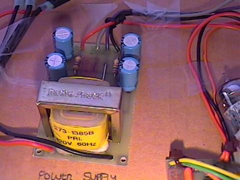 |
Here is the power supply PCB all assembled. The transformer I used is a RadioShack #273-1385B 300mA 120VAC to 12.6VAC stepdown transformer, available off-the-shelf at RadioShack. There were originally some mounting tabs on it at the bottom, which I cut off. The internally mounted transformer idea got trashed! Being a cheap transformer, it created too many problems with radiated EMI, which causes hum. Instead, I am using a 13VAC wall wart to power the circuit, which makes it one of my quietest pedals. |
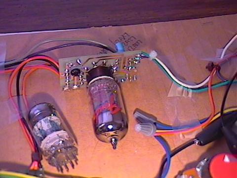 |
Here is the preamp tube section after assembly. The bias control is the 10K trimpot on the upper lefthand corner of the PCB. I tried a variety of tubes - An unknown brand German manufactured 12AU7, NOS JAN Phillips 12AT7, Sovtek 12AX7WA and an unidentified vintage ECC83, Tungsram, I think. I decided that I like the JAN Phillips 12AT7 the best. In the finished product, to avoid potential problems, I used a tube shield. My new circuit uses a similar layout for the physical mounting of the tube socket. I decided that the tube shield wasn't necessary, and is detrimental to the operation of the tube in my new design. |
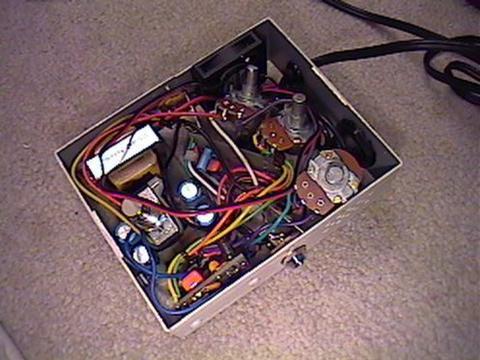 |
Here is everything inside of the enclosure, with the top removed. I used a 4"x5"x1.5" aluminum utility box for the enclosure. It has a removeable top and bottom, which comes in handy for this circuit. It was a real challenge figuring out how to get all of this stuff to fit inside this box. My new layout is a little bit neater, but it's still difficult to fit all of this stuff into an enclosure. Sometime I would like to rehouse the circuit in a Hammond 1590BB enclosure. |
 |
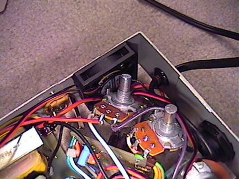
Here is another view of the circuit, viewed from the bottom. The footswitch is just below the power supply PCB. I was originally going to have the preamp tube rising up vertically through a hole in the top of the enclosure, but I changed my mind. The preamp tube PCB doesn't move once the bottom is on. My new preamp tube socket is physically fastened to the enclosure. My construction techniques have gotten a little better over the last year. |
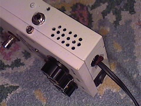 |
I decided to give the box some ventilation, since the transformer and tube produce some heat. I simply drilled a series of 1/8" dia. holes in both sides. At bottom right, you can see the rocker style on/off switch. The power cord plugs into a 120V wall receptacle. The switch and permanently attached power cord have been deleted and a power jack added in their place. |
 |
I got carried away and added a cooling fan. This is a 12VDC 0.13 amp brushless CPU cooling fan (RadioShack #273-240) that runs at low speed via a voltage dropping resistor. I glued it to the side of the enclosure with super glue. Hmmm... this may be the world's only fan cooled stompbox! (Sorry, it's the mechanical engineer in me getting carried away) The fan draws air in from one side, through the box, across the tube and then out. Fan noise is barely audible when it's running, thanks to the slow fan RPM. I removed the fan. It was not due to it being impractical, but more to do with it causing problems with my wah pedal on the opposite side of my pedal board. Since ventilation is now passive, I doubled the amount of holes on the sides. |
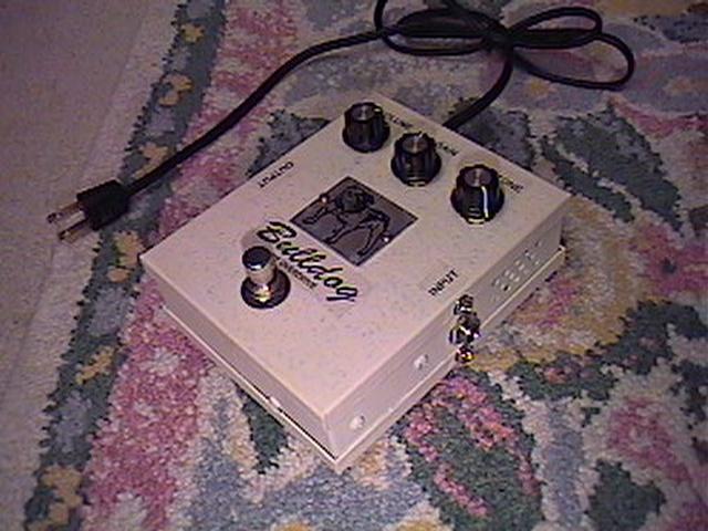 |
Here is a view of the finished product. The bulldog plate comes from an old Bulldog Electric Company electrical panel tag. I had it in my desk drawer for over ten years and I finally found a use for it. I cut it down to suit. It's hard to see in this picture, but the paint finish is crackled, the result of using latex house paint and a 1500 watt blow dryer. There is a protective clear coat covering the entire enclosure. I am currently in the process of adding a Millenium II Bypass, an LED status indicator. I decided that I wasn't totally pleased with the finish on it, so I stripped it down to the original grey color. |
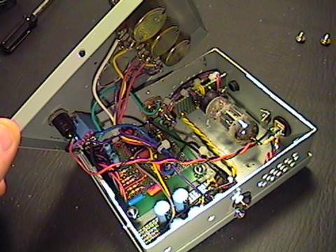 |
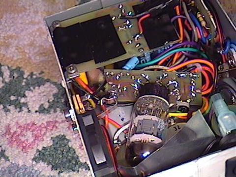
Here is the interior of the rebuilt circuit. The IC circuit board is at lower left and the filter cap/rectifier section is at lower right. I used an LF353 opamp at first, but decided on a JRC4558D opamp in the end as it seems to sound a little bit smoother. I used shielded wire for the input and output jacks for good measure and I also found it necessary to use a grounded circuit input true bypass scheme to prevent the circuit from oscillating when bypassed and somehow finding its way, faint as it was, into the bypassed signal. It wasn't a big problem, but in the right context, it would cause feedback problems. |
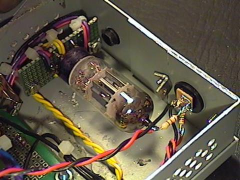 |
Here
is the preamp tube mounting. You may be wondering how I put the tube socket
on a piece of perfboard, right? Well, if you have some perfboard with plated
thru-holes, you can take a PCB mount socket, set it on the perfboard, and
bend the little legs to the nearest hole. Then, you solder the socket to that
hole. Next, from the same side as the tube socket, take some wire and pull
it thru a hole right next to the place where the leg is soldered, fold it
over and solder it to the hole where the leg is soldered. This creates an
electrical contact between the wire and the socket. It works! . |
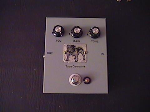 |
Here is the way it looked after reworking it. The indicator light is made by Dialite and works on 5 volts. It is connected to the 13VAC power supply through a 4.7K current limiting resistor. Not shown in this picture is an added treble cut switch just above the gain control which switches in a 0.015uF cap to ground on the circuit output to smooth out the highs a little bit and makes the tone control a little more friendly. |
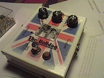 |
And here is the final version of this project. The British flag seemed to be the obvious choice for something named "Bulldog". |
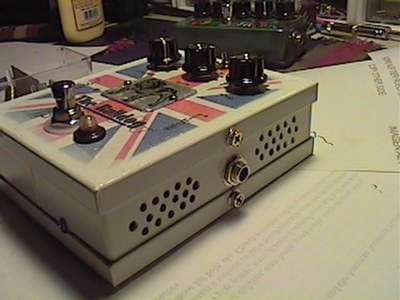 |
Here you can see the series of ventilation holes that I drilled in the enclosure. |