Real McTube II Clipping Characteristics
By Paul Marossy
Last
Updated 8/4/04
One evening, I thought it might be interesting to see the clipping
characteristics of this circuit with an oscilloscope. What I found
was kind of interesting. All the waveforms shown below are with the
volume control set at 3:00 and a sine wave input at a frequency of 600Hz
with 20dB attenuation. The tube that I used for this study was a Sylvania
12AU7. The waveforms didn't really change with frequency in terms
of the clipping that occurred, only the amplitude changed when the gain
was increased. I tried several frequencies - 80Hz, 600Hz, 1kHz and 2.5kHz,
they all looked the same. I didn't go through the entire audio range since
electric guitars can only produce frequencies in the region that is between
82Hz and 3kHz. The scope used is an old workhorse, a Tektronix 453. The
Volts/Div control was changed as necessary to get waveform to fit on the
CRT screen for each picture. Slope was set at "+". Below is some pictures
of the waveforms that I saw. These are what they look like at the output
of the circuit.
This is the waveform with the gain control set at 9:00.
Pretty much the sine wave as it comes from the signal generator.
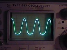
This is the waveform with the gain control set at 11:00.
The bottoms are getting a little more rounded now.
The tops still look pretty much the same. The beginnings
of a little bit of asymmetrical clipping.
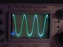
This is the waveform with the gain control set at 1:00.
Now the bottoms are getting a little more squashed.
Amplitude of signal gets a little larger, too.
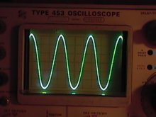
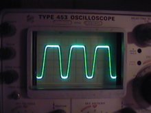
This is the waveform with the gain control set at 3:00.
Pretty much your classic tube clipping. Amplitude of signal
is even larger now with virtually no more asymmetric clipping
evident.
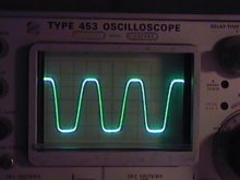
This is the waveform with the gain control set at 5:00.
Look Ma, major asymmetrical clipping! Or is it? Actually,
what you are seeing here is a change in pulse width. The
amplitude of the signal is the same as in the previous picture,
giving the appearance that the tops are now clipped more than
the bottom.
It is interesting to me how the waveforms change as the gain control
goes through its rotation. I don't fully understand why this circuit
clips the way that it does, but I suppose it has something to do with
the clipping characteristics of the tube and/or the circuit itself.
One individual has suggested that the first stage stays unclipped at
lower gain settings and has more headroom on the positive cycle to cause
the second stage to clip, accounting for the initial asymmetry on the
bottoms of the waveforms. This also appears to indicate a change in the
polarity (inverted signal) after passing through the first gain stage.
As you turn up the gain, the signal amplitude increases enough to where
the first stage begins to break up. When this happens, the first tube likely
limits the signal more on the saturation side, which is inverted on the
output of the second stage. The effect is that the second stage is then
amplifying the asymmetry of the first stage after it begins to break up.
At a later date, I will do the same experiment with a 12AT7 and a 12AX7
to see how they compare with the 12AU7. I will also investigate what is
happening after the first gain stage as well to see what is happening with
the signal at that point.