My Modified Real McTube II
Last updated 1/21/05
Unfortunately, the creator of the Real McTube, Fred Nachbaur, has recently passed away. He lost the battle with cancer from what I hear.
You will be missed Fred. Sometime before he passed he had contacted me to tell me that he liked my implentation of the circuit!
I built the Real McTube II mainly because I was intrigued by the use of two 500mA
120VAC/12V transformers to create a B+ voltage of approximately 140V. I also do like the clean sounds
that are available, and with my modifications, the overdrive sounds really good, too. The circuit is basically the stock circuit, except for the few changes that I made that probably worked
out great more so by sheer luck than a brilliant stroke of genious. The changes that I made consist of
changing RV1 & RV2 to 1M audio pots, instead of the 500K as specified on
the schematic
. I also omitted R9 (100K in parallel with RV2). The change
that had the most impact was the transformers that I used - two 300mA 120VAC/12.6VAC transformers from
RadioShack. Due to transformer inefficiency and lower current capability, my starting B+ voltage measured
110VDC instead of the specified 140VDC on the schematic. This ends up supplying about 30-35 volts less to
the plates of the tube, but in my opinion, this is a good thing. The clean tones sound awesome! And the
overdrive sounds you can get sound pretty nice, too. I am currently using a Sylvania 12AU7 in it. Using
a 12AX7 will give you mondo gain, but not the rather oversaturated overdrive sound in the soundclip at
the Real McTube II page. I have yet to try a 12AT7, but I bet it would sound good, too. You can read more
about this circuit
here
.
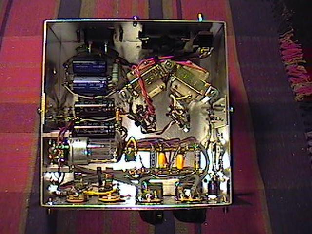 |
Here is a view of the insides. It is built in a recycled aluminum enclosure that originally measured 6"x6"x3" high, which I cut down to 2.5" high. Wiring is point-to-point using terminal strips. Circuit is very quiet the way that I laid it out. |
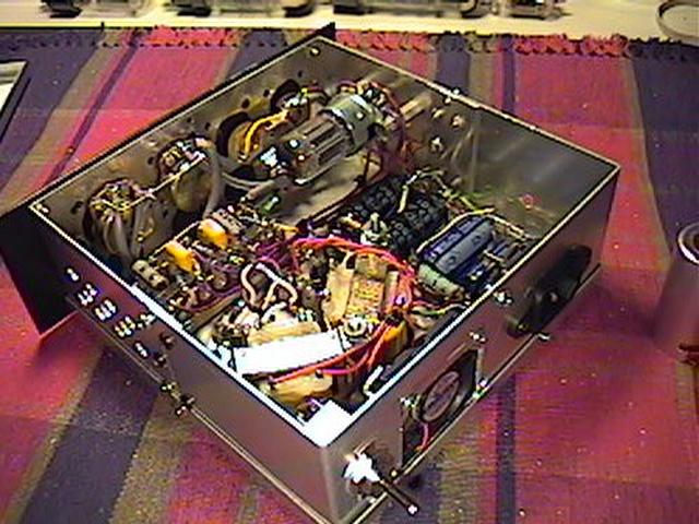 |
Here it is a view from the rear. I have a CPU cooling fan installed, but I haven't decided if I'm really going to hook it up or not. To the right of that is a 3-prong IEC socket for safety's sake. On the sides of the enclosure, I drilled a series of holes to allow for a little passive ventilation. |
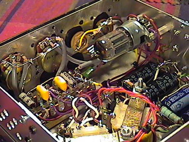 |
Here is a closer view of the tube socket mounting and wiring. |
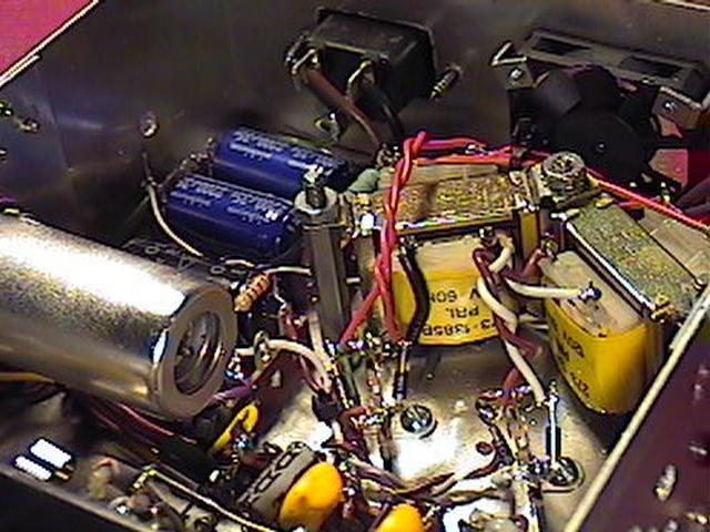 |
Here is a closer view of the transformers. These are "PC mount" transformers mounted upside down on standoffs. The two "trees" in front of the transformers are the rectifier diodes mounted to a terminal strip. |
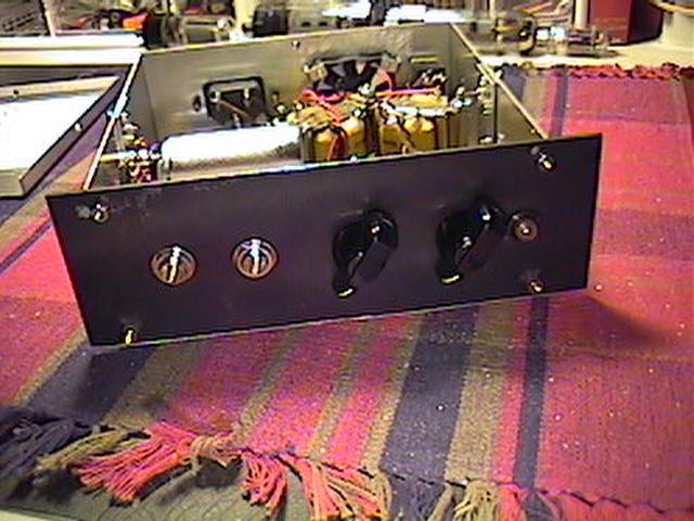 |
Here is a front view. The faceplate is made from a piece of approx. 1/16" thick black anodized aluminum sheet. Pilot light is a panel mount LED made by Dialite. The next step was to mount it in an enclosure. |
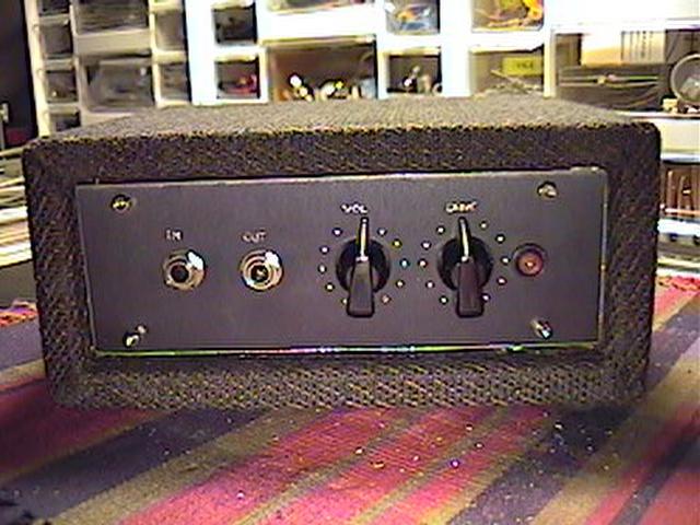 |
Here is the finished product. Since I am using this project as a "studio fixture", the enclosure is made from 1/2" particle board and is wrapped with the same material as my Firefly tube amp. There are four small rubber feet on the bottom. The lettering on the front was done by hand by scratching off some of the anodizing with a sharp object. It's not as perfect as I would like, but it works. The dots around the chicken head knobs were made with a Dremel tool equipped with a small drill bit. I used just the point of the drill bit to remove the anodizing and make a small indentation on the surface. I may add some small amp corners at a later date. |
Overall, I am very happy with the results. This circuit seems to be fairly versatile. It can go from mild overdrive to pretty heavy sounding, cleans up pretty well when you roll back the volume knob of your guitar, and the tone control has a pretty big effect on the sound.