Seymour Duncan Convertible Channel Switch Wiring
Last updated 3/15/03
Here is some details of the channel switching arrangement:
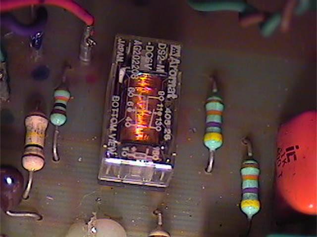 |
Channel switching is acheived by using a relay. |
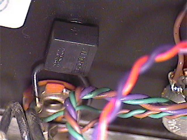 |
Rear view of switch. It is wired to a mono 1/4" jack. |
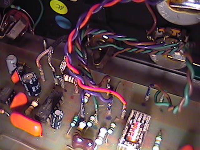 |
The two wires from the 1/4" jack are connected to the PCB just in front of the relay. |
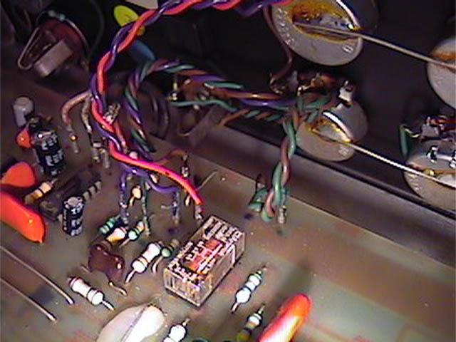 |
Here is another view of the wiring. |
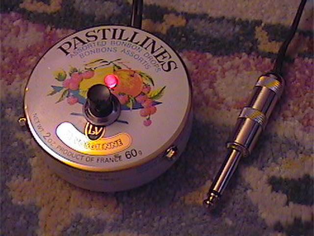 |
Here is a channel switcher that I made out of... Yes, it's a candy tin. Actually, with the switch installed, it is pretty sturdy. It has three rubber feet on the bottom so it doesn't slide around. I'm still debating if I'm going to paint it or not. |
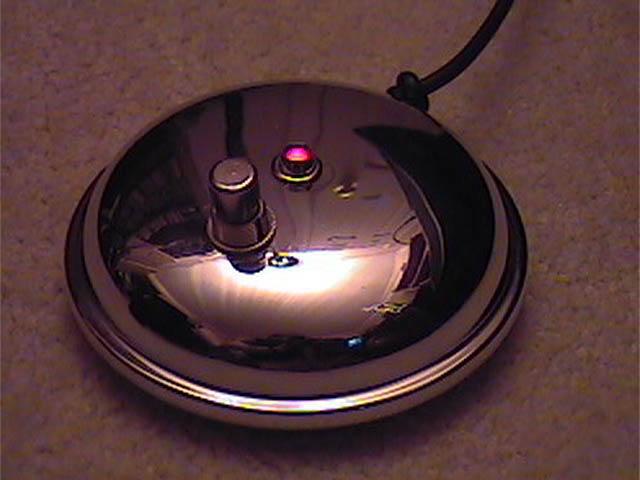 |
Well, I found something better. This is a lid to some kind of kitchen gadget I found at a thrift store for 75 cents. The footswitch is a Carling SPST. The original footswitch looks like this: |
Well, I figured out how it works... As long as the switch on the amp itself is set to the right position, you can use any SPST stompbox channel switcher with a 1/4" male plug. It did fool me the first couple of times... I was thinking it had to be something complicated... I was kind of guessing without a schematic to look at at!
Here is how the circuit works: The pedal switches the relay (plus red LED, and further controls the transistor) and the transistor switches the green LED. When the footswitch makes contact, the red LED is grounded, as well as the relay coil in series with it, allowing enough current to pass from the B+ at the top through the horizontal resistor, through both the relay coil & the red LED to energize both. The cap is there to quench spikes when the relay coil is de-energized. The red LED & coil were grounded before but it was through the relatively high resistance pair of series resistors around the base of the transistor, and that would not let enough current flow to activate the relay or light the red LED. However, when that relatively small current was flowing through the base resistors, it was serving to bias the transistor on which allowed enough current to pass through the 470K resistor and the green LED to light it while the red one is off. When the footswitch makes contact, it is so much easier for the current to go straight through it to ground, nothing more passes through the biasing resistors and the transistor shuts off the green light.