Chassis Pics Of My Matchless Spitfire Clone
By Paul Marossy
Last updated 6/1/04
Here is some pictures of the chassis with some commentary.
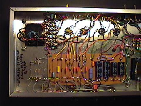 |
Here is the left side of the chassis. The output transformer is at upper left. I got the idea of using the screw down terminal strips from looking at a chassis pic of a Matchless DC-30. I found out that using these requires some thought as they can contribute to problems with induced hum. |
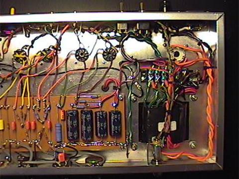 |
Here is the right side of the chassis. The power transformer is at lower right. The choke is just to the left of the power transformer, underneath where the filter caps are. Power and standby switches are at upper right, as well as the fuse holder and IEC socket. The ground wire from the IEC socket goes to the chassis directly below the socket. |
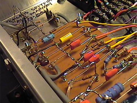 |
Here is a closer view of the turret board. It is mounted to the chassis using 1/2" stand-offs. I used a ground buss for all preamp connections to ground and for the phase inverter connection to ground. The tone control connection to ground is made at the point where the ground buss connects to the chassis. I used a star ground for the rest of the connections to ground. |
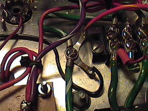 |
Here is a view of the star ground point. The filter caps, power transformer secondary center tap, 6.3V heater center tap and output transformer center tap all connect to this point. |
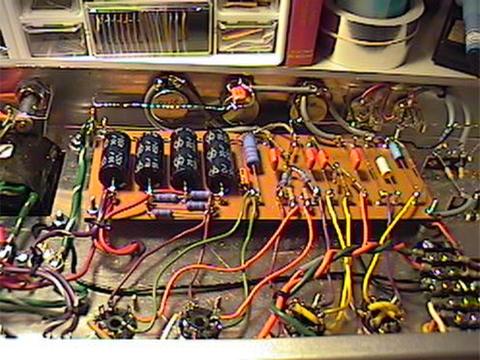 |
Here is a view of the back of the pots. I used shielded wire from the input jacks to the preamp tube and for all wires from the pots to the turret board. I also installed a 0.01uF ceramic cap from the ground lug on the input jacks to ground to shunt any possible RFI to ground. |
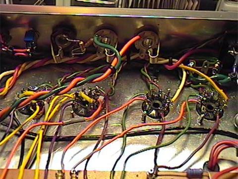
| Here is a view of the tube sockets and the speaker jacks. All of the 6.3V heater wiring and output transformer primaries are bundled together behind the sockets, below the speaker jacks. The 6.3V wiring is run in parallel to each tube, as is in the real amp. |