Matchless Spitfire Based Tube Amp
By Paul Marossy
Last updated 12/2/06
The Matchless Spitfire is a 15 watt tube amp that had
been out of production for several years, and is once again being offered by Matchless. It was also the forerunner to the currently manufactured Lightning. They seem to be pretty rare compared to their other amps. In fact,
I have never seen a used one up for sale, yet. A lot of DIY amp builders seem to like this amp, and I knew that it
sounded really nice. So, for my second ever build, I decided to build a clone of it using quality
parts and similar construction methods to the original. This amp appears to be somewhat similar to a Vox AC15, using a pair of EL84s in a push-pull configuration, but
without the tremolo section and is allegedly a Class A amplifier, like the Vox AC15 is supposed to be. In reality, the Spitfire is AB with a high bias current. A schematic for it can be found here.
Below is a step-by-step outline of my project.
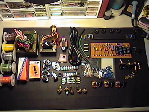 |
Here is some of the parts needed for the amp. There is quite a few parts required for even a simple amp such as this one. What is shown here is the electronics portion of the amplifier. |
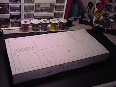 |
Here is the raw chassis with a full
size drilling template before any openings have been made. I used AutoCAD to create the template and to also check out the fit of all the parts inside of the chassis beforehand. It took about 90 minutes to mark up the chassis and make all of the necessary openings. The enclosure I used is a Hammond 16"x8"x2" aluminum chassis which I purchased
from Mouser.com for
$21. |
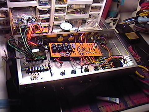 |
Here is the chassis with the wiring about 25% complete. One of the main differences between my amp and a real one is that mine uses a turret board for most of the circuit, which is a kit that I purchased off of ebay. To cut the square openings for the transformers, I used a Dremel Tool with a thin cutting wheel. It took about four blades to cut the three required square openings, but it made some nice, clean cuts. A file cleaned up the rough edges where needed. For the tube socket openings, I used a trick I heard about at a guitar amp forum - a 3/4" to 1" size wood drill bit, depending on the socket you use. It works on aluminum because it is a soft metal, and it makes a pretty clean hole. |
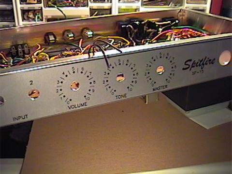 |
Here is the front of the chassis with graphics applied. I used my usual stickyback method for the graphics. Covering the graphics is a sheet of thin, clear plastic which gives a nice looking finish while protecting the graphics underneath. It can be a little brittle when you are working with it, so you have to cut and drill it carefully. |
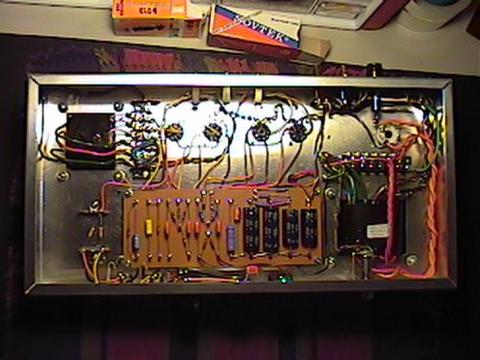
| Here the initial wiring is complete. It took about 12 hours total to get to this point, and about an hour creating the chassis layout in AutoCAD. The indicator lamp is powered with the 6.3V heater supply. I tried to use the same general methods that Matchless uses for bundling the wires, etc. I still have a new appreciation for amps that are wired point-to-point or use turret boards. It's kind of an art when you are used to PCBs and strip board. It's rather tedious and labor intensive for complicated circuits. No wonder they charge so much for PTP amps! |
 |
Here is the bottom of the chassis, looking at it from the front. The power transformer, output transformer and choke are the 15 watt set available from WestLabs.com . While a little expensive at $167 for the set, these are replacement or OEM transformers for Matchless and Vox amps and are very nice. |
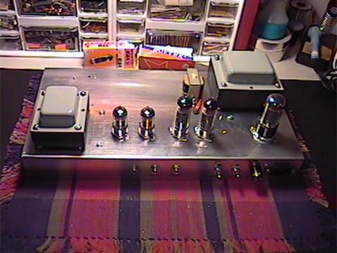 |
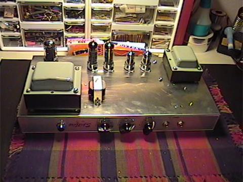
Here is the bottom of the chassis, looking at it from the rear. The power and standby switches were purchased at RadioShack. They seem to be seem to be satisfactory for this application in terms of quality and they meet the ratings needed to be used with this amp. Tube compliment is follows (left to right): 12AX7, 12AX7, EL84, EL84, 5AR4. Preamp tube shields not shown in this picture. |
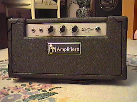 |
With the chassis done, it was time to build a cabinet. I built it out of 3/4" particle board. All the outside edges were rounded to a 1/4" radius by hand (I was wishing that I owned a router!) Here is the finished product. It is covered with some recycled Tolex that I pulled of the enclosure I recycled for my Firefly. On the inside surface of the top of cabinet, I installed some shielding made of thin sheet aluminum. The cabinet follows the general Matchless look. The logo is of my own design, just to give it the appearance of a commercially manufactured amplifier. The overall dimensions are 17.5"x9.5"x9" high. Weight is about 28 lbs. | 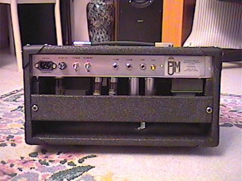 |
Finally, here is a view of the back of the finished amp. I painted the inside of the enclosure black. There is also a small 12VDC powered fan to ventilate the chassis a little bit. It runs off of a diode bridge tapped off of the 6.3V heater supply and operates at about 8VDC, making for a quieter fan while still moving a decent amount of air. I also installed a switch to turn it off for when "in the studio". | 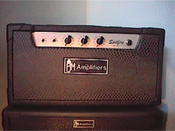 |
About two years after I was done messing around with this amp build, I decided to redo the front panel as I had always felt that it was bland, and besides, I actually messed it up around the control area when I made it the first time. | 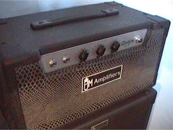 |
I like the contrast between the case and the front panel. While I was at it, I also made a new nameplate and recessed it into the front panel. I think it looks a lot classier this way, too. | 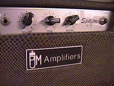 |
Here's a closer view of the front panel and nameplate. I've been contemplating making this build into a combo amp and adding reverb to it, but I am still undecided on actually doing it or not. |
Here is the specs for the Westlabs transformers used in the Matchless Spitfire:
At start up, I checked all of my B+ voltages, and they measured pretty darn close to the schematic. In my amp, actual B+ voltages measured as follows: A - 350V, B - 347V, C - 314V and D - 321V. All of the other voltages measured very close to what is indicated on the schematic as well.
So, you're probably wondering, how does it sound? Great! It's a little bright, but perfect with a guitar that has somewhat of a dark tone. And it is pretty darn loud for a 15 watt amp. Now, this amp doesn't produce that much distortion, but it does break up very nicely and it also reproduces all the nuances of your guitar. Because the amp is really nice sounding, it seems to allow you to be more expressive because the tone is so nice.
15 watt Power: T542030 Cutout 2" x 2-1/2", 575 volt ac ct 100 ma, 6.3 volt 4 amps, 5.0 volt 3 amps
15 watt Choke: T541949, Inductance 6 Henries
15 watt Output: T541954 Cutout 1-3/4" x 2-1/4", Primary Impedance 4000 ohms, Secondary Impedance 4, 8 & 16 ohms