DIY Function Generator
By
Paul Marossy
Last updated 06/16/03
I
just finished building this project. Although there are kits you
can buy, such as the one KitsRUs.com offers (which produces a pseudo-sinewave),
I thought I'd build my own instead just for the challenge of it.
The circuit is simple. It uses a
single IC chip, the ICL8038 function generator chip which
produces simultaneous sine, square and sawtooth wave forms. There
are relatively few parts in the circuit - just two resistors, one
transistor, five trimpots and the function generator chip. The
ICL8038 can operate on a unipolar power supply between 10 and 36
volts DC, and it can also be used with a bi-polar power supply.
I built it per the schematic and it works, except I had to change
the 1M resistor between the power supply and the square wave
output to a 2M trimpot to get the waveform to function properly
and be at the right amplitude in comparison with the sine and
sawtooth waveforms. Check out the pictures below.
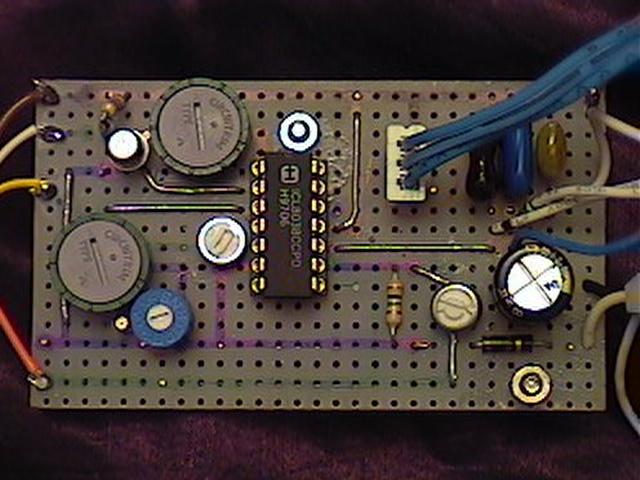 |
This is the top of the circuit board. I used some non-coppered perfboard I had lying about to build the circuit on. Whenever I use perfboard, I like to mark up my perfboard with some fine point Sharpie markers and get all the connections worked out before I actually construct the circuit. I find it easier to do it this way. |
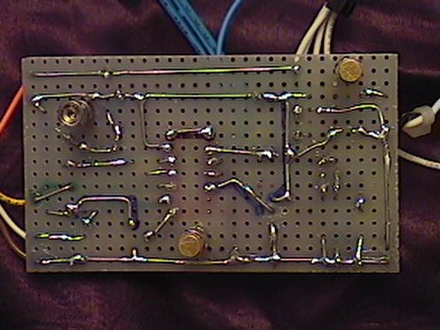 |
This is the back side. It's a little more challenging using this type of perfboard over the copper padded type. |
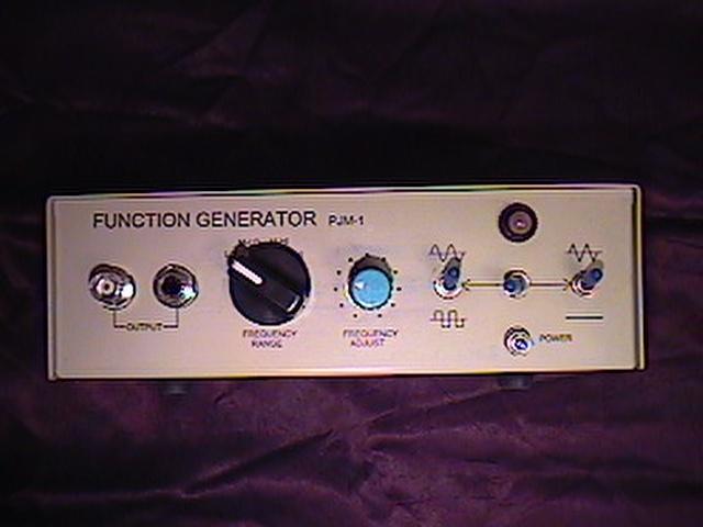 |
Here is a view of the front. The enclosure comes from a defunct 4-way data switch box. I gutted it and created some graphics for the faceplate. It measures 7.5"x2.25"x5" deep. |
For the
frequency range switch, I used a recycled rotary switch from an
old parallel port A/B switch box. To make it work with this
circuit, I had to disassemble it and rearrange the insides a
little bit, but now it does exactly what I want it to. (I know, I
could have just bought a new rotary switch, but I had this switch
lying around...) Since I am using a single female BNC jack and a
single 1/4" jack wired in parallel, I decided to use three
SPST switches to switch between the different waveforms. One of
the switches will be a on-center off-on type. I figure the middle
position would make a nice "kill switch" which will
prevent any waveforms from reaching the output jacks. I like the
idea, because if I don't want any output, I can just flip that
switch and leave the unit powered up. Of course, one could just
use another rotary switch with a SPST switch that could act as a
kill switch as well. I used the SPST switches mainly because I
had a bunch of them lying around waiting for a new home...
This homebrew function generator isn't as fancy or accurate as
the ones that are on the market, but for a do-it-yourselfer
hobbyist type, it's adequate. I have found that the sine wave
isn't totally accurate when I switch between frequency ranges,
but I have incorporated a pot which corrects any waveform
offsets, so it still quite useable and pretty accurate. Not too
bad for a $20 project.