D.I.Y. Guitar Effects Prototyping Board
Last updated 07/03/03 by Paul Marossy
After
18 months of building several guitar effects circuits, I finally
feel like I have learned enough to start doing some breadboarding
and experimenting with some of my own ideas. I first saw a
prototyping board several months ago through the guitar effects
forum I frequent, Aron Nelson's Stompbox Forum at http://www.diystompboxes.com
The best way to experiment is by using a "breadboard".
A breadboard is simply just some molded plastic with a series of
openings 1/10" apart, connected in rows by metal clips on
the underside of the breadboard. All you have to do is slide
wires and component leads in these holes to make your circuit, no
soldering is required as the breadboard makes all of the
connections for you.
Since guitar effects circuits all have some things in common,
such as input and output jacks, volume and/or gain controls, tone
controls, etc., you can permanently mount the breadboard, some
spare pots and jacks to a piece of wood and hard wire them to the
breadboard. I made this whole thing for under $10, since most of
the parts were given to me or were lying around in my parts bin.
The whole project might cost $50-65 if you had to buy all of the
parts new.
Below is some pictures of what I call my "guitar effects
prototyping board".
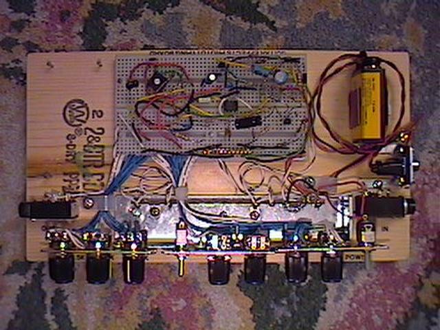 |
Here is a top view. Nothing fancy, it's just meant to be effective. The wood is a piece of 1"x6" pine that I had laying around the garage. It is about 10" long. The breadboard is nailed to the wood. The space to the left of the breadboard can accommodate a smaller breadboard (RadioShack #276-175), which can come in handy if I run out of room when building more complex circuits. I installed a 9V battery clip and battery holder, a power switch, and an LED to indicate if the power is on or off. The bottom has one adhesive backed cork pad on each corner. |
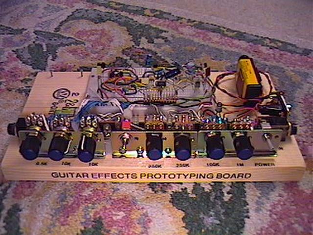 |
This is a view from the front. I labeled all of my pot values, input and output jacks and ground points. I used (1) 0.5K, (2) 10K, (1) 100K, (2) 250K and (1) 1M pots. I used some knobs that I purchased at RadioShack. The metal brackets that the pots are mounted in were given to me by a friend. Those brackets are in turn mounted to a bracket which came out of my previous printer which died, and was immediately cannibalized for parts... |
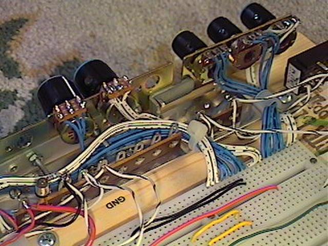 |
This is a view from the back. The wires connected to the pots are three-wire ribbon connectors, which work excellent for pots. The other end of the wires were tinned with a little bit of solder and then inserted into the breadboard. The pots will be permanently connected to the breadboard. I used some point-to-point terminal strips for things like the wires from the input and output jacks, and connections to ground. The input and output jacks are the enclosed type, the body of the jack is super-glued onto the wood board. Labels were made with my wife's label making machine. |
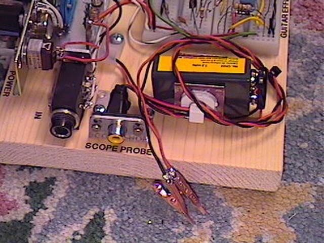 |
I also installed an RCA phono plug jack for an oscilloscope probe that I created, which has an male RCA plug at one end instead of the usual scope probe stuff. There are two wires that go from the RCA jack to alligator clips, one of the wires has a 1M series resistor to keep from loading the circuit too much. (I will see how this works, I may make it a 10M if it seems to load the circuit down) Since I have a two channel scope, this setup enables me to see how a signal looks going into one part of a circuit and what it looks like after a another part of the circuit. |
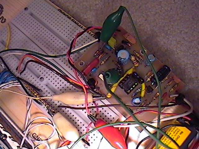 |
This prototyping board also doubles as a circuit testing fixture. You can quickly connect to the various pots and the input and output jacks for quick testing and troubleshooting. This is a great time to make use of a DIY Audio Tester Probe , a simple and effective troubleshooting device. |
So
there you have it. I hope this gives you ideas on how to build
your own sleep deprivation device, uh, I mean guitar effects
prototyping board. (After having this thing done for less than a
week, I have already designed my own circuit, which I am still
tweaking)
Having a breadboard can also be a very useful tool to hear how
changes you make to a circuit will sound. It's great for messin'
with cap values and types, there is really no limits as to what
you can do with this thing, except your imagination. In just two
evenings, I have learned quite a lot! Since I am a hands-on sort
of person, it helps me with reconciling abstract audio
electronics theory with real world results. I am really glad I
built this thing! Not so sure about the wife, though. :)
Oh, and make sure you get one or two extra breadboards, one may
not be enough once you start getting ideas! I have a nice Global
Specialties Proto Board 2 that was given to me that will serve as
an independent breadboard, if I have two projects running
simultaneously. (You never know....)
My Benchtop DIY Audio Oscillator
My DIY Adjustable Voltage Power Supply