A DIY Adjustable Voltage Power Supply
By
Paul Marossy
Last updated 08/23/04
If
you build / breadboard electronic circuits a lot, an adjustable
power supply really is a great help. I built one from a kit, made
by KitsRUs.com ,
Kit No 68.
It's a very easy circuit to build, and it provides up to 30 volts DC at up to
1.5 amps of current. It's a textbook adjustable voltage circuit, and can accept
either AC or DC inputs due to an on-board rectifier. I added a few things to
make it a very useful tool. Below are some more details.
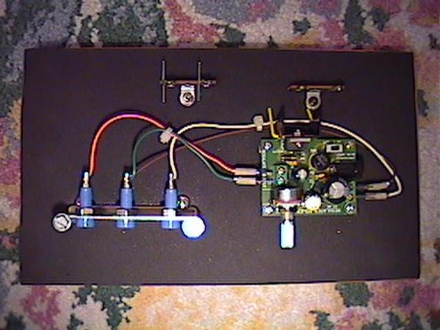 |
Here is the view from above. The board on the right is the adjustable power supply. The three blue jacks to the left are for my digital multi-meter probes. Everything is mounted to a 3/8" thick piece of plywood which measures 8"x5". The black surface is 1/16" thick self-adhesive neoprene rubber. |
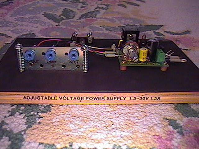 |
This is the front. I used slip-on wire terminals for easy removal of the wires going to the DMM probe jacks. |
 |
Here is a close-up of the power supply board. There is a point-to-point style terminal strip behind it. |
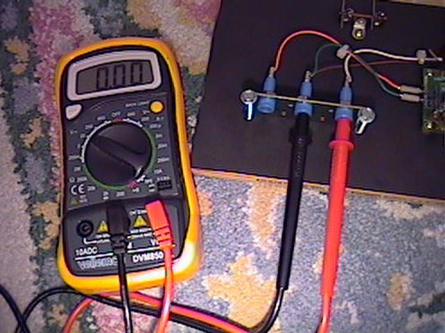 |
Here it is with my DMM plugged in. The middle plug is a common ground. The one on the right measures the input voltage. The one on the left measures the output voltage. |
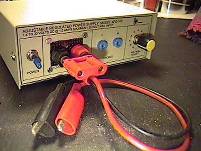 |
About a year after I built this circuit, I decided that I wanted it to be in an enclosure. I recycled another computer A/B switch box for my enclosure. |
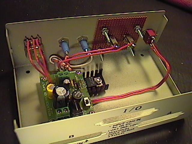 |
Here is a picture of the inside of the enclosure. |
A practical and
very inexpensive way to power your circuits in the R&D phase. Most of the parts for this
project could be found at your local RadioShack if you wanted to build it from scratch.
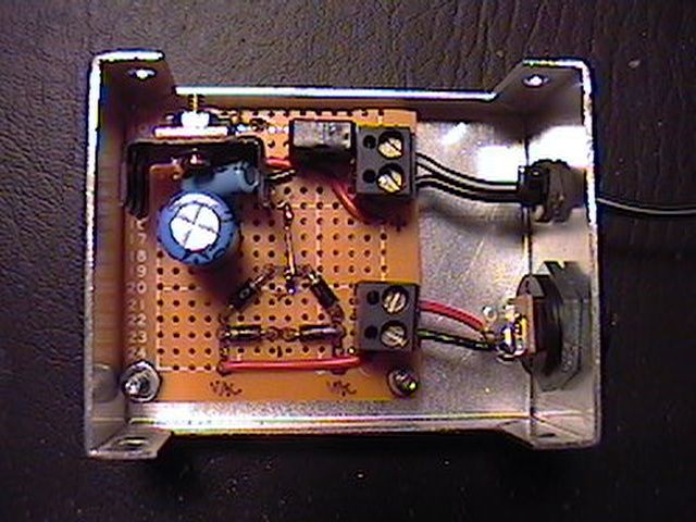
Here
is an example of a scratch
built adjustable power supply using a LM317 regulator.