 The Tektronix 453
Oscilloscope
The Tektronix 453
Oscilloscope
By
Paul Marossy
Last updated 06/21/03
Thanks to Bill Den Beste for helping me get the facts straight.
My
father-in-law gave me this classic analog oscilloscope (Thanks!)
so I could learn more about my main hobby, electronics. It was
sitting in his garage for many years and had dust caked on the
face and inside of it. Amazingly, I cleaned it up, turned it on,
and it worked just fine! Only one thing was wrong with it - one
indicator light was burned out. I had to do some minor
adjustments to it, which consisted mostly of adjusting the
astigmatism for the sharpest view, both gain controls and the
vertical step attenuators, but that wasn't too hard to do.
Comparatively speaking, all of the adjustments I made were minor
in nature. Knowing the age of the scope, I wasn't too sure
Tektronix would be of much help, but I contacted them anyway
about an owner's manual for the scope. As I thought would
probably be the case, they wrote back and told me that it was
long out of production, and that support for it was discontinued
in 1982. They did, however, give some websites to visit. There
are a few sites that helped me get the info that I need, such as
the Tektronix
Resource Site and Chris Nystrom's Site.
I made up this little webpage on this scope because it is
somewhat of a technological marvel. Most of the earlier model
Tektronix scopes had lots of vacuum tubes in them, but some were
solid state. The original Model 453 is mostly solid state, with
the exception of a few " nuvistors " (solid state
triode) and one vacuum tube for each vertical input on the CRT.
My 453 is 99% solid state, all of the nuvistors have been
replaced by FET's. In my scope, the PCB's actually have markings
Q____ (for transistor) in place of where a V____ (thermionic
device) would be. I suspect there was a design change in
1968-1969 because some of the PCB's inside my scope are
copyrighted 1965, 1969. The Model 453A is basically the same
scope, but the as I understand it, as in the later model 453's,
the nuvistors were replaced by FET's and the most obvious
difference is that the CRT screen is taller by two graticule
lines.
Inside there are about 1,200 capacitors, 1,200 resistors,
hundreds of diodes and transistors, a high vacuum cathode ray
tube (CRT) and other components. These are tough scopes, the fact
that mine is 35 years old and still working great (and was used
by the US Armed Forces) says a lot all by itself.
They come up for sale on ebay once in awhile, and are very
reasonably priced. (I picked up a second one, serial number
040057, on ebay for $26! Unfortunately, it appears that the high
voltage transformer is bad, but not a bad price for a spare parts
source.)
I like these older scopes because you can actually work on them
yourself, if you know what you are doing. Newer isn't always
better. Since I had the scope apart I took some pictures of it.
Below are some of those pictures and descriptions of various
parts of the scope.
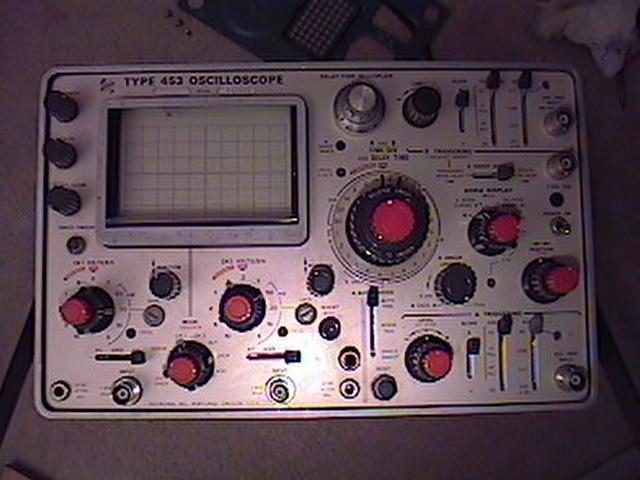 |
Here is the front showing all of the controls. This scope has two channels and many features which makes it quite versatile. The CRT screen originally had a protective cover and a smoke grey lens, both of which are missing. I fashioned a smoke grey lens out of a TDK cassette case. It helps make the screen easier to view. It is installed in this picture. Originally, there was also a controls cover, which is also missing. Serial number is 037389. |
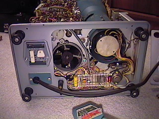 |
This is the back, with the cover plate removed. Here I was cleaning the cooling fan passageway. On the cover plate, there is a filter frame for a little filter which is supposed to keep dust out of the unit. There some mains fuses just above the power cord. There is also a dual power scheme, 120/240 VAC. Power consumption is 92 watts. At the bottom, you can see some ceramic strip construction. |
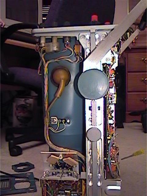 |
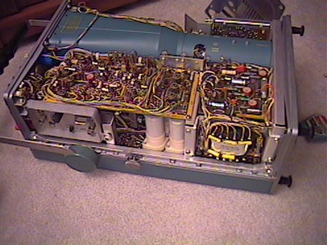
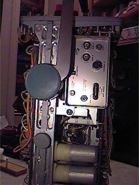
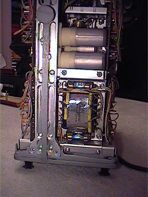
This is a view of the left side with the covers removed. The long tubular thing is the CRT and its enclosure. Overall dimensions are as follows: Height - 7.25 inches, Width - 12.5 inches, Length - 20.5 inches with front cover, 22.5 inches with carrying handle in carrying position. Weight with cover - approx. 29 lbs. |
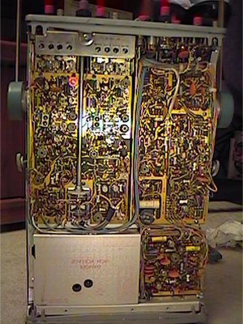 |
This is a view of the bottom, with the cover removed. High
voltage stuff (8kV) is under the metal cover at lower left. Here is where
the high voltage transformer (T930) can be found. There are three seperate PCB's here. |
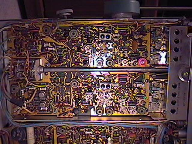 |
One of those PCB's on the bottom is the Vertical Preamp Board, shown here. |
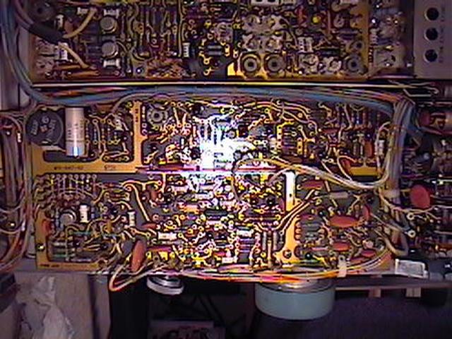 |
The next PCB on the bottom is the A Sweep Board, shown here. The power rectifier diodes are hiding underneath this board. Another place where ceramic strip construction is utilized. |
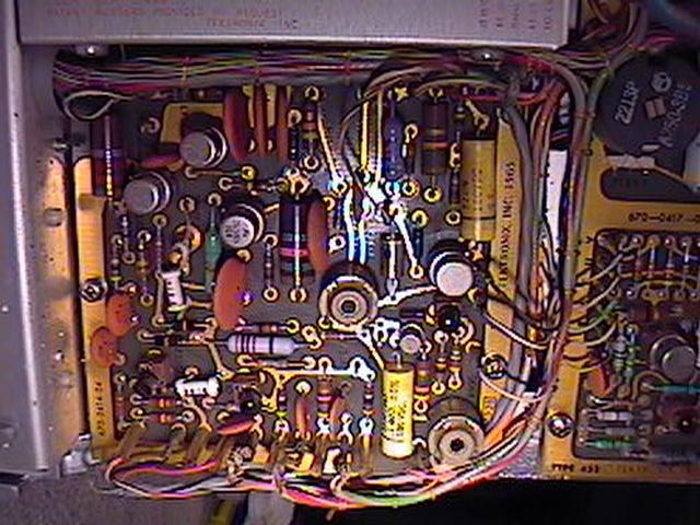 |
The last PCB on the bottom is the Z-Axis Amplifier, shown here. The high voltage power supply adjustment pot (R900) is also on this board. Power for the CRT is created by an oscillator circuit on the low voltage side which is fed into the primary of a transformer (T930) which bucks up the voltage to about +8kV for use by the CRT circuit. If there is a problem with the oscillator circuit (Q930 and associated circuitry), the CRT will not function. This is a fairly common occurence in these scopes as they get older. |
 |
Here is the right side, with the cover removed. You can see the CRT enclosure at the top of the picture. The Low Voltage Regulator Board is just above the power transformer, at lower right. To the left of the Low Voltage Regulator Board is the B Sweep Board. |
 |
This is the right side showing the side panel controls. |
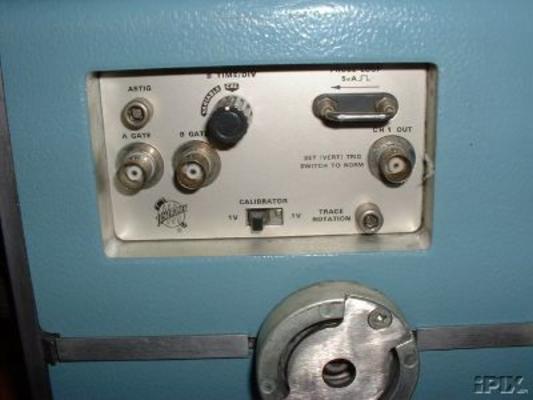 |
This is a close up of the side panel controls. |
 |
The side panel swings out after the removal of one screw. |
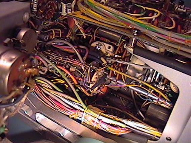 |
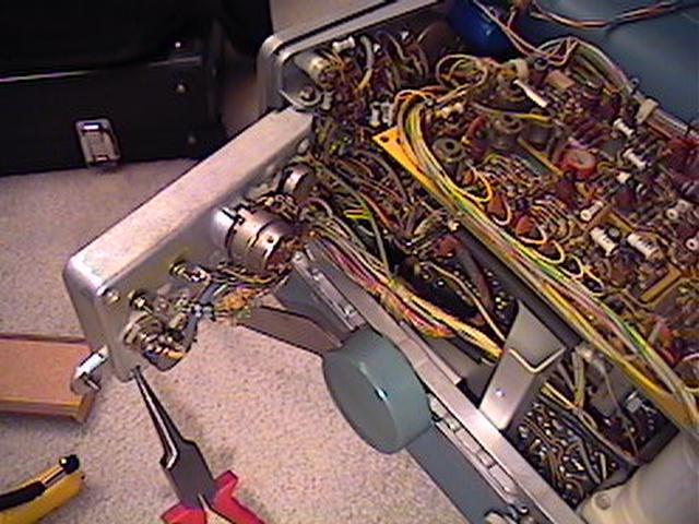
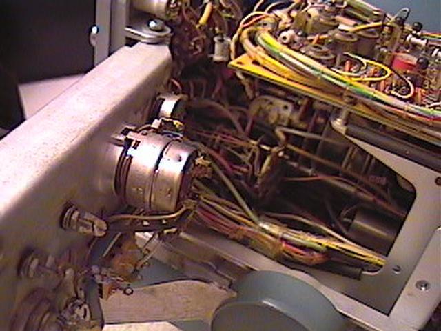
Here is what it looks like beyond that side panel when it is swung out. There are a lot of wires inside this thing! |
 |
Here is another view of part of the right side showing the power transformer and power filter capacitors. |
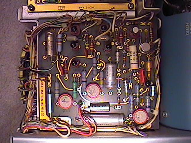 |
This is a picture of the Low Voltage Regulator Board. If your 453 suddenly dies, after checking the fuses, this is the place to look. There is a +75, +12 and -12 volt section on this board. These supply power to virtually every circuit in the scope. I have had one occassion when my scope suddenly stopped working properly. I tracked down a bad transistor in the +75 volt supply. The output of the +75 volt supply also has some effect on the +150 volt unregulated power supply. Underneath this board are three power transistors. |
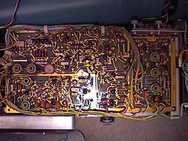 |
This is a picture of the B Sweep Board. |
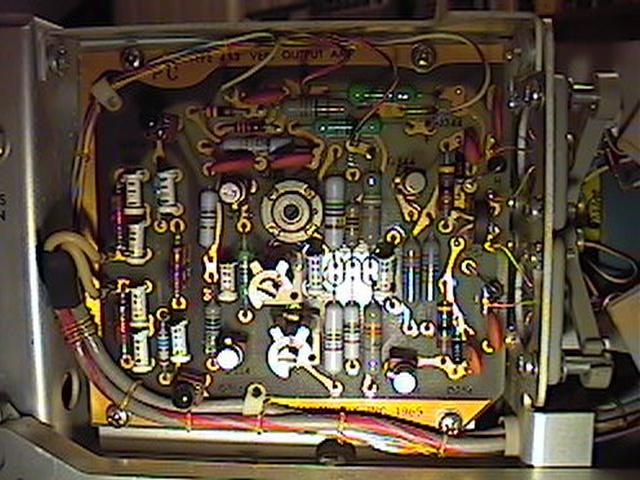 |
This is a picture of the Vertical Output Amplifier Board. |
 |
There are yet more things embedded in this unit. It is quite a technological marvel. I am very impressed by its design, ruggedness and reliability. This scope is still considered to be a very good scope, even by today's standards. |
If you pick up this
scope, get the owner's manual for it! They come up for sale on ebay once in
a while, and I bought a CD with the US Army Technical Manual TM 11-6625-1722-15
(1972) on it in PDF format for $10. (It is best to get an original Tektronix
owner's manual because some of the color-coded information on the CD has been
lost) The main reason to get an owner's manual is to help you learn how to operate
it properly. And get a service manual, too. This scope is a very complex piece
of equipment and having the manuals can be very helpful. For example, if you
want to have it officially calibrated, there are 74 points to check and adjust
if required. Or if a transistor goes bad (thank goodness, they are in sockets)
the electrical parts list will tell you what it can be substituted with. Plus
there are schematics, exploded views and other helpful tools in the event that
something needs to be repaired or replaced. In today's digital world, I would
have no problem recommending this scope to any electronics hobbyist. With a
50mHz bandwith (or higher), it is quite sufficient for any kind of audio work
and other types of analog circuits. Heck, even some digital stuff, too.
There are many, many probes available for scopes. I mainly use a pair of Tektronix
P6108 10x passive probes since they do not load the circuit very
much when I'm poking around and looking at waveforms. A 1x probe is generally
acceptable for audio work, but I like using the 10x probes.
One thing to note is that when you do the simple 1kHz calibration, don't be
alarmed if the vertical lines on the square wave don't appear to be the same
width as the horizontal lines. This is due to the fact the trace intensity varies
according to the writing rate. In other words, it is because the speed at which
the dot moves determines the number of electrons that arrive at the phosphor
per second, which in turn determines the intensity of the beam. The horizontal
speed is a constant, so when the trace is drawing a vertical line, it has to
move a long way in a short time, thus it is not as bright.
In conclusion, this old scope is one of those things that falls in the category
of "they don't make 'em like they used to". This is not to say that
current Tektronix products are junk, only that it is virtually impossible to
work on them yourself and they are packed with propietary parts which you have
to pay a premium for. And the 453 was designed and manufactured before the advent
of CAD/CAM manufacturing which is the exact reason why you can work on these
things. Kind of like the old tube guitar amps I work on. The 453 is quite a
piece of engineering.