Building a Firefly 1.5 watt Tube Amp
By Paul Marossy
Last updated 2/18/04
Here is a cool
little tube amp project that is a good first time build for those brave enough
to venture into tube territory. It is Doug Hammond's Firefly,
Rev. 3, a push-pull 1.5 watt tube amp utilizing two 12AX7 preamp tubes and a 12AU7 preamp
tube in a self-split power tube configuration. One of the 12AX7 tubes is in
a switchable cascode boost circuit. Not only is this an interesting and unusual
way to use preamp tubes, but it also sounds great! My Firefly is built per the Rev. 3 schematic, except for an added resonance control. The resonance control I used is a 5K pot with a built-in switch. It can be switched in or out of the circuit. The cap value is flexible and can be any value between 10uF and 47uF.
This is actually my first tube amp build. I've wanted to build a tube amp for at least a year before I built this project. Below is some details of how I approached making what I like to call my "Deluxe Firefly".
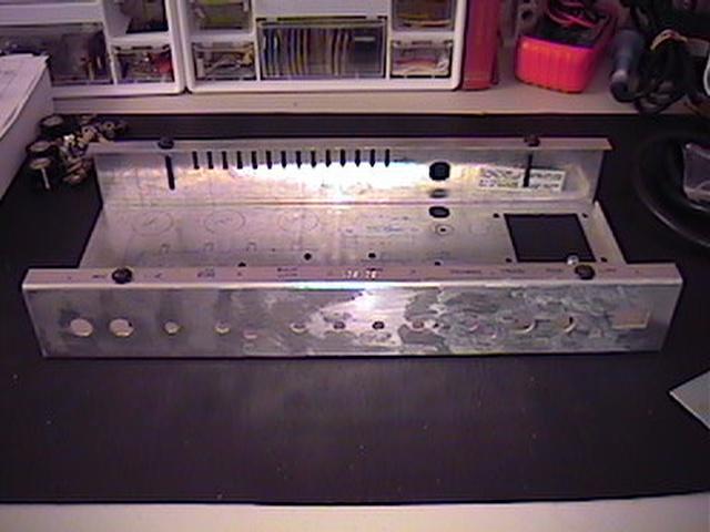 |
When I made my first speaker cabinet, I cannibalized a cheap Crate bass amp that had a hum I just could not rid of. This is the raw chassis from that amp before my modifications to it. It was a real pain getting the sticky stuff off of the front of the enclosure after removing the faceplate. It measures 14"x6.5"x2" and is made out of aluminum. |
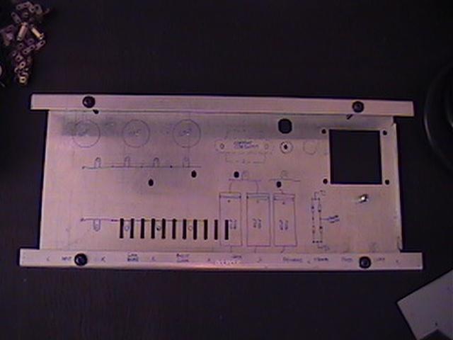 |
Next, I got an extra fine point Sharpie marker and designed a chassis layout. I marked out where everything was going before drilling any holes. One immediate problem was that large opening where the power transformer was. |
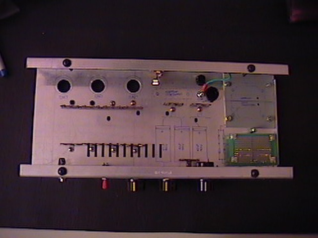 |
Here is the chassis with the terminal strips installed and most of the holes drilled. I found a way to cover the large opening... |
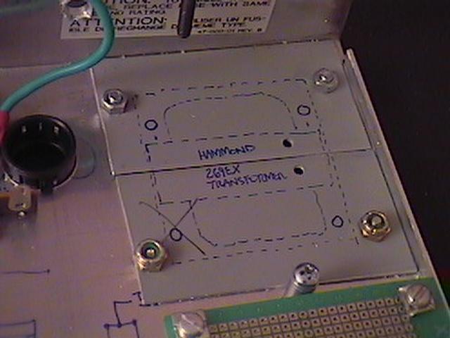 |
To cover the hole where the power transformer was, I cut some pieces I had leftover from an aluminum enclosure that I had cut down and covered the opening with them. To the left is a hole with a black plastic insert for the new transformer wires. The green perfboard will house the rectifier diodes and wiring from the new power transformer, and wiring to the standby switch. The power transformer I decided to use is a Hammond 269EX, which has a 190-0-190V center-tapped secondary and a 6.3V heater filament all in one transformer. |
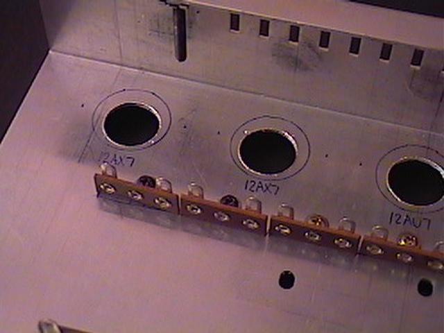 |
Here is the openings for the preamp tubes. To drill these holes, I used a trick I heard about at a guitar amp forum - a 3/4" or 7/8" size wood drill bit, depending on the socket you use. It works on aluminum because it is a soft metal, and it makes a pretty clean hole. A rat tail file cleaned up the edges where needed. |
 |
I covered the face of the chassis with four layers of 2" wide aluminum tape, known as "metal repair tape", sold at places like Home Depot. It has lots of uses. This will get covered with some graphics which I designed via AutoCAD. |
| Here the wiring is about 25% complete. Still waiting for parts before I can continue... I have a new appreciation for amps that are wired point-to-point. It's kind of an art when you are used to PCBs and stripboard. It's rather tedious and labor intensive for complicated circuits. No wonder they charge so much for PTP amps! |
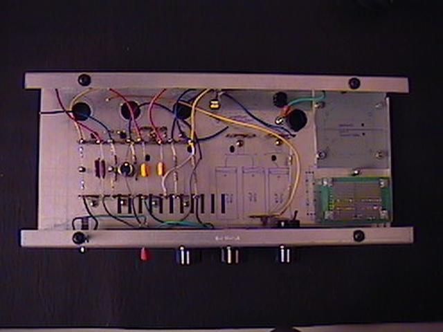
 |
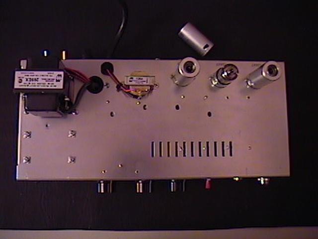
Here the chassis wiring is complete. I used wire from a dead computer power supply, which is rated for 300 volts. It gave me lots of different colored wires and didn't cost me anything. I kept all wiring runs as short as possible and followed good design practice everywhere that I could. One small change I made is powering the indicator lamp with the 6.3V heater supply instead of 120V as shown on the schematic. |
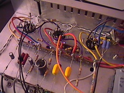 |
Here is a close-up of the preamp tube sockets. It was somewhat of a challenge getting all this wiring soldered up in such a small area. |
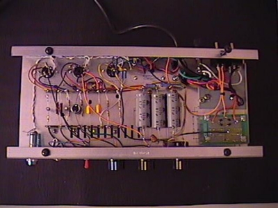
 |
Here is a view of the bottom of the chassis. I used tube shields for the preamp tubes for a variety of reasons, but mostly because this a relatively high gain circuit. I wanted to minimize problems with any kind of noise as much as possible. |
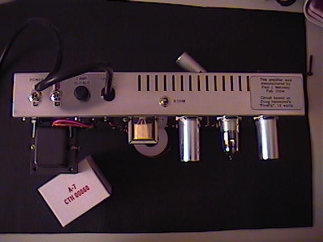 |
Here is a view from the back. When I stripped down the original chassis, I polished the back and bottom surfaces of the chassis with an SOS pad. It leaves a nice and shiny surface. The power and standby switches were purchased at RadioShack. They seem to be seem to be satisfactory for this application in terms of quality and they meet the ratings needed to be used with this amp. |
 |
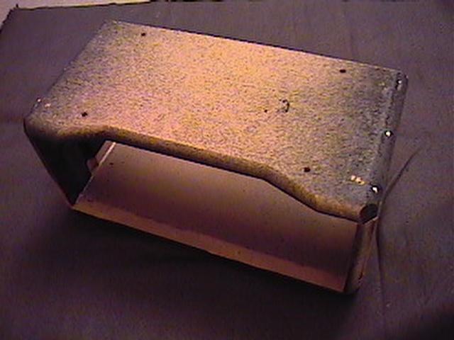
With the chassis done, it was time to build an enclosure. I decided to use the enclosure I had leftover from the Crate bass amp I cannibalized for my speaker cab project. This is what it looked like before I did my surgery. |
 |
After peeling all of the old Tolex off, I marked up the enclosure for cutting down to size with a jigsaw. Here is the enclosure after I was done cutting and reassembling the pieces. It didn't take very long to do all the cutting and it was pretty easy, all things considered. |
 |
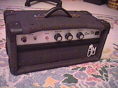
Here is the enclosure with a new cloth covering. It is applied with some spray adhesive. I used the corners that were on the original cabinet. The grille cloth also comes from the same bass amp cabinet. I cut it down to the size that I needed. The logo is my own design, just to make it look like a commercially manufactured amp. You can't see it this picture, but there is shielding on the top and sides of the enclosure where the chassis is. |
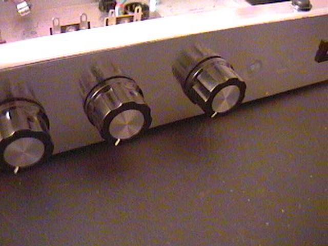
 |
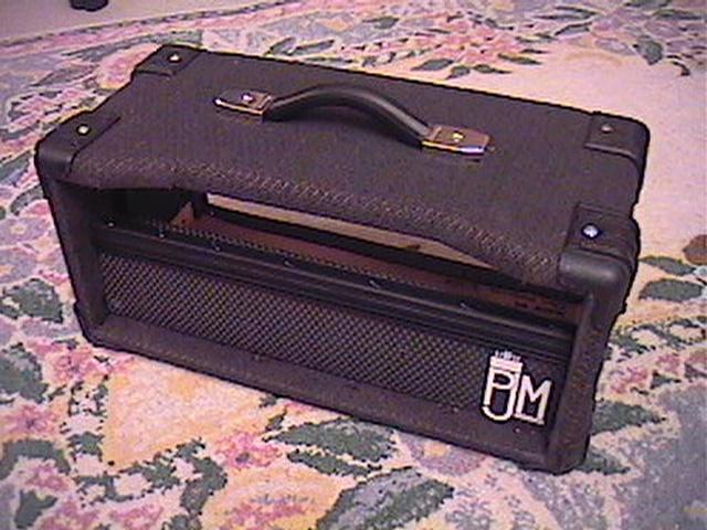
Here is the finished product. The overall dimensions are 16"x8"x7.5" high. Weight is about 12 lbs. The graphics were done with my usual sticky back method as shown on my Building Stompboxes page. It's not perfect, but it works pretty well for my purposes. | 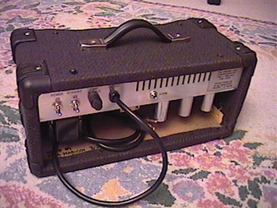 |
Finally, here is a view of the back of the finished amp. I have since painted the inside of the enclosure black. |
Despite its simplicity, it's not an easy project to build compared to building stompboxes, nor is it very cheap. Even with all the things I recycled for this project,
it still cost about $120 out of pocket. It took several long evenings to complete this project, probably about 32 hours total over a 6 day period. But, in the end,
I think it is worth the time and effort. It turned out pretty well for my first tube amp build. I think that it helps that I have been poking around in tube amps for a
while and have noticed the things common to all designs, which I employed in building this amp.
As always, it's a good idea to double check all of your wiring and components to make sure everything is connected together properly before firing it up for the first time.
I made a couple of mistakes in my wiring, it's not too hard to do. When I first turned my FireFly on, I had a horrible hum. Since hum problems are usually always related
to grounding issues, I double checked all of my connections to ground and realized that I didn't connect the two 100 ohm resistors on the tube heater wiring to ground, nor the filter caps.
Dumb mistake number one. After fixing that, it sounded great, but seemed very loud. So I checked all of my B+ voltages. They were measuring roughly twice what they were supposed to.
After checking out my wiring on the secondary side of the main power transformer, I realized that I made another mistake. I inadvertently wired the center tapped secondary wrong.
After fixing that, I was in 1.5 watt tube amp heaven. In my amp, actual B+ voltages measured as follows: B+1 - 299V, B+2 - 265V and B+3 - 254V. Fortunately, for either of my errors,
no damage was sustained by any of the components. Always double check your wiring!
After playing around with this amp for a few days, I have found a couple of simple tweaks that may be worth trying that involve no changes to the circuitry itself. By simply using
different combinations of preamp tubes, you can, to a degree, change the tone of the amp. Try combinations, like two 12AU7, one 12AU7 and one 12AT7, two 12AT7s, one 12AX7 and one 12AU7,
etc. The 12AU7 connected to the output transformer should not be changed, it should always be a 12AU7 type. You can also get interesting tones by using various distortion pedals,
as you can hear from the soundclips at the
About a week after I was done, I thought about adding a "sag switch", which would kind of simulate a tube rectifier. This is a very simple mod to do. All you have to do is get a DPDT switch and place it in series with the B+ supply and wire it so that it switches in a 100 to 200 ohm, 1 watt resistor. I personally like the tube rectifier "sag" feel, but others like the tight bass of solid state rectifiers. This little mod would give you the best of both worlds. But, then after the fact, I was made aware that the amp is a Class A amplifier, not AB. In a Class A amp the output tubes will demand the same average DC current for the whole cycle. In Class AB the average DC current demand will change and will depend somewhat on the amplitude of the signal on the grid. This changing current demand is what allows a tube rectifier or sag resistor to provide compression. So, if the current demand doesn't change, then there isn't really any dynamic interaction with the sag resistor or rectifier to cause this effect. But, it was a good learning exercise, nonetheless. And it does change the character of the sound a little bit, so maybe it's not a total waste of time. I settled on using a 1K ohm resistor, which lowers the B+ voltage by about 12 volts and it seems to me to give just a touch of compression, and it kind of softens up the sound some without a noticeable reduction in volume. It is a subtle change in tone, but you can hear it if you listen closely.
Another thing that I did do was add an impedance switch to enable use with a 4 ohm or 8 ohm cabinet. This is very easy to do with a transformer that has a multi-tapped secondary such as the Hammond 125A. I did this because I wanted to use a 2x8 speaker cab with this amp. A 2x8 cabinet sounds really good with this amp, in my opinion.
I know, I know, I sure got carried away with all these mods for such a low powered amplifier, but this amp is a good platform for learning about tube amps and little mods you can do to them. I like versatility... maybe next I'll build something a little more complicated, like a Fender Bassman or a Marshall Plexi clone, if money and time allows.