Building a 5-7 watt Octal Fatness Tube Amp
By Paul Marossy
Last updated 1/29/05
Here is a cool
little Class A single ended tube amp project that has a great tone and puts out about 5-7 watts depending
on the power tube used. It is Doug Hammond's version of the Octal Fatness,
which can use several different power tubes with the right output transformer. Tubes that
could be used are 6L6GC, 5881, 6V6, EL34, KT66 or even a 6AR6 with an adapter (if using the
same socket as the other tubes listed). This amp uses a 6SJ7 and a 12AX7 in the preamp section.
I built mine pretty close to the schematic with a couple of minor deviations. One was adding
adding a volume control at the input and the other was a gain boost switch which simply switches
the cathode bypass cap on the 12AX7 to ground for a little bit of boost. I did this mainly
because I had a switch on the front of my recycled chassis that I wanted to find a use for. It's actually
a useful mod. I also added the volume control because I had a place on the the chassis for
a volume control, so I stuck one on there. I like lots of knobs anyways.
This is my third tube amp build. Once you've started, it's kind of hard to stop! Below is some details of how I approached making my Octal Fatness.
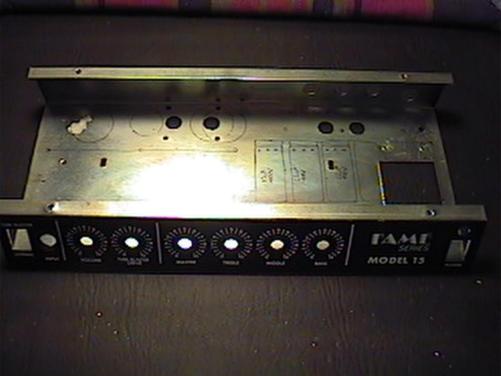 |
This one started out as a raw chassis pulled from a cheap solid state amp. It was given to me free of charge, I just had to pay for the shipping costs. Here it is before I made any modifications to it. What's cool about this one is that the graphics are already on the faceplate. And it just happens to be marked for all the controls that I need for this particular amp. (How cool is that?!) It measures 12.5"x6"x1.75" and is made out of steel. Here, I have marked it up with an extra fine point Sharpie marker and designed a chassis layout. I marked out where everything was going before drilling any holes. One immediate problem was that large opening where the power transformer was. | 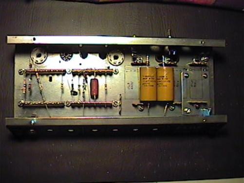 |
Here is the chassis with the terminal strips installed and most of the holes drilled. I found a way to cover the large opening. Covering the hole where the power transformer was, I used a leftover aluminum plate that goes on the bottom of a plastic RadioShack project box, a perfect fit. I reused existing chassis openings wherever possible. |
 |
Here the wiring is about 25% complete. To drill the holes for the tube sockets, I used a trick I heard about at a guitar amp forum - a 3/4" to 1" size wood drill bit, depending on the socket you use. Normally, you would use this trick on an aluminum chassis because it is a soft metal, but I've found that it also works on a steel chassis as long as you drill a 1/8" pilot hole and drill the hole at a slow and steady speed. It makes a pretty clean hole. A rat tail file cleaned up the edges where needed. The power transformer I used is from an ebay auction - a NOS power transformer made by Better Coil & Transformer in 1963, which has a 280-0-280V center-tapped secondary and a 6.3V heater filament all in one transformer. |
 |
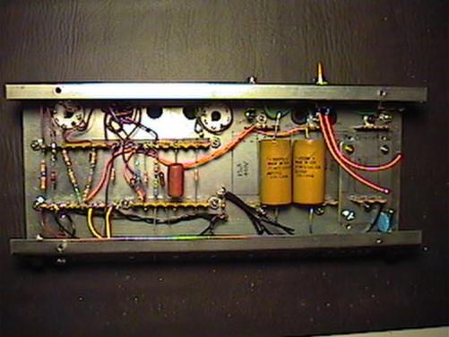
Here the chassis wiring is complete. I used a few different colored wires to help keep things straight. I kept all wiring runs as short as possible and followed good design practice everywhere that I could. I used an LED manufactured by Dialite for the indicator lamp which is powered with the 6.3VAC heater supply. As you can see, it was a challenge fitting all of the circuitry inside such a small enclosure, but I was able to achieve a good layout in spite of that. |
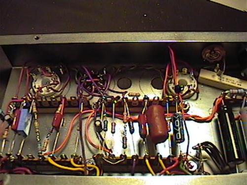 |
Here is a close-up of the
tube sockets. It was somewhat of a challenge getting all this wiring soldered up
in such a small area. The preamp section is something of a Frankenstein, as I used
a bunch of caps I had lying around and some odd value resistors in series and
stuff like that. You can see the star ground at the lower right corner of the picture. About six months after I built the amp, I replaced all of the coupling caps with new ones rated for 400V. |
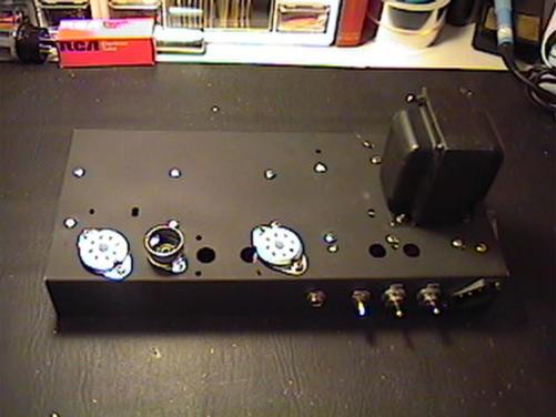 |
Here is a view of the bottom of the chassis, before the output transformer was installed. |
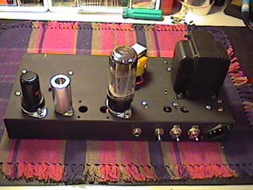 |
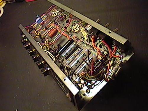
Here is a view with the output transformer installed. I painted the rear and bottom with flat black paint, which matches the paint on the face of the chassis, covers up the old graphics and the scratches, making it like like a brand new chassis. The power and standby switches were purchased at RadioShack. They seem to be satisfactory for this application in terms of quality and they meet the ratings needed to be used with this amp, in my opinion. I used a tube shield for the preamp tube. I wanted to minimize problems with any kind of noise as much as possible. The 6L6 tube was temporarily in the socket when I was determining how big the enclosure needed to be to accomodate a 6L6 if I wanted to give it a try. |
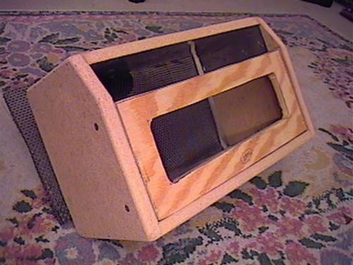 |
Here is the enclosure before any coverings were applied. The majority of the enclosure is constructed from 5/8" particle board. The face is constructed from 1/2" plywood and will be covered with some grille cloth. I made an opening in the face to allow for some ventilation, which will be provided by a small 12VDC fan drawing air through the face. Lining the top of the enclosure where the chassis will sit is a piece of thin aluminum shielding. It is held on by some staples. The enclosure was cut with a jig saw and the edges were rounded by hand with a rasp. It took about 2.5 hours to construct the enclosure. | 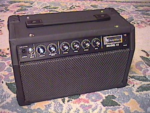 |
Here is the finished product. The overall dimensions are 14"x7"x8.25" high. Weight is about 14 lbs. I made up some graphics to cover up the unwanted graphics on the right side of the chassis face. Control knobs are as follows, from left to right: volume, drive, master, treble, middle and bass. The switch on the left is for my bypass cap mod on the 6SJ7 and the switch on the right is for the cooling fan. The Tolex-like covering I used is some high density vinyl upholstery material I purchased at a local fabric store. It is glued on with some 3M spray adhesive. It took about 2.5 hours to cover the enclosure and install all of the hardware. | 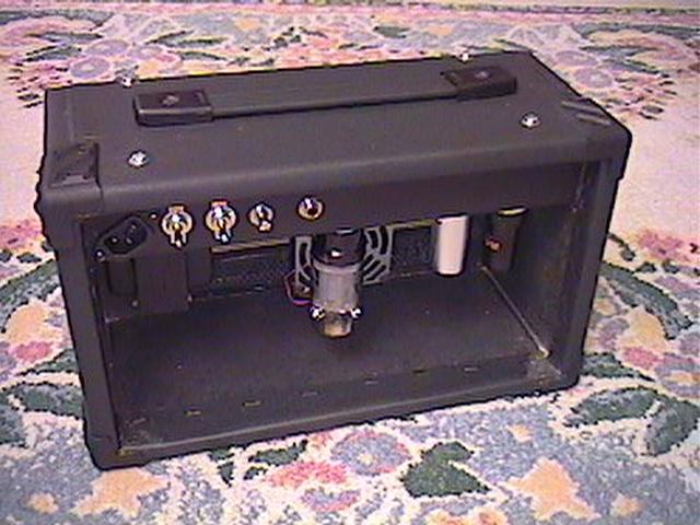 |
Finally, here is a view of the back of the finished amp. I painted the inside of the enclosure flat black. The IEC socket is at an angle - it was the only way I could install it in order to reuse existing chassis openings for the power and standby switches and to keep AC wiring far away from everything else. As in all of my amps, there is a cooling fan, which runs on about 9V after being full wave rectified off of the 6.3V heater supply. | 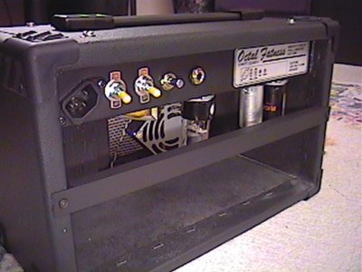 |
This is a 3/4"x1/2" aluminum L-channel that that I modified to use as a brace across the back to protect the tubes from harm. I painted it flat black to match the chassis. I added this about 6 months after I finished the project. It was something that I intended to do all along, but put off for a while because I wasn't sure of the best way to do it. I also added a little nameplate on the back of the chassis. | 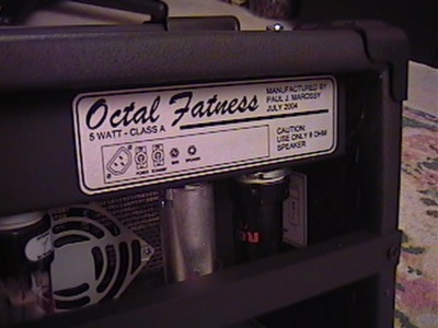 |
Here is little closer look at the nameplate. Using my usual method, I created the graphics on AutoCAD and printed it out on "sticky back", a clear self-adhesive applique. I placed that on top of a piece of self-adhesive aluminum foil, known as "metal repair tape" at places like Home Depot. This gives it a more professional appearance as well as reminding me what ohm speaker cabinet to use with it. |
As always, it's a good idea to double check all of your wiring and components to make sure
everything is connected together properly before firing it up for the first time. Always
double check your wiring!
In my amp, actual B+ voltages measured as follows: At diodes - 356V, B+1 - 348V, B+2 - 291V,
B+3 - 247V and B+4 - 238V. I used a 6V6 power tube, a NOS RCA 6SJ7 and a NOS RCA 12AX7.
The amp sounds great, and a wide ranges of tones can be had by tweaking the controls. It has
beautiful tube amp distortion! Really, I honestly don't care for that many tube amp distortions,
but this one does sound very nice. I think it has something to do with the 6SJ7 metal can
pentode on the input (you can get them for about $5 a pop on ebay). On a clean setting, I
can tweak the EQ to get a very "acoustic" sound. For distortion/overdrive, by playing with
the master, volume and drive controls, I can a very wide range of sounds ranging from pretty
clean to almost metal kind of sounds. A lot depends on your guitar and what kind of pickups it
has in it, too. That switcheable bypass cap mod on the 12AX7 adds a little more flexibility,
too. Not a huge difference, but with the gain control turned up far enough, it is pretty noticeable.
About six months after building the amp, I decided that it just had too much hum with the
master volume turned up high, so I decided to find the source of the hum. The input and
speaker jacks were already isolated types, so that wasn't a contributor to the problem. I checked all of the solder joints, connections to ground, replaced all
of the coupling caps and reversed the primary on the output transformer. There was some improvement
after these measures, but the hum was still too much for my liking. I finally tracked down the
main offender - the cathode bypass cap on the 6SJ7 seemed to be too small. I replaced that with a
47uF cap and took a second look at the power tube bias and that solved the problem. Now it's as quiet as my Spitfire, with just a little hiss
with all of the controls turned up 100%. Some people have noted that 6SJ7 tubes can be real quiet or have
a fair amount of hum, so your mileage may vary.